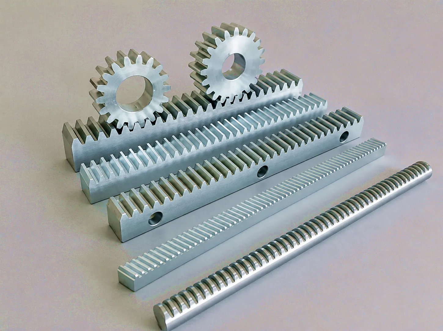
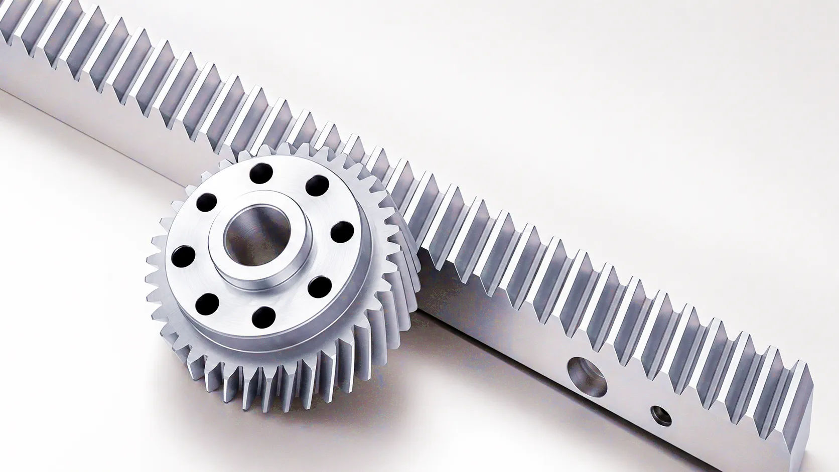
 Rack and pinion systems sit at the heart of countless machines that shape how modern Britain manufactures, moves, and builds. At its core, a gear rack is a straight-toothed bar that meshes with a rotating pinion gear to convert rotational motion into linear motion — or the reverse. This deceptively simple principle underpins everything from CNC machining centres in Sheffield’s advanced manufacturing corridor to automated portal cranes operating at port terminals along the Humber estuary. Despite the apparent simplicity, the engineering that goes into producing a dimensionally stable, hardness-consistent gear rack is far from trivial. The tooth profile must conform precisely to involute geometry, the material must be selected with both load-bearing and surface-fatigue requirements in mind, and the rack-to-pinion backlash must be controlled within tight tolerances if the application demands positioning accuracy. In the UK market, where industries from defence supply chains to food processing automation demand reliable motion control components, the quality of a gear rack can be the decisive factor between a machine that runs profitably for a decade and one that requires costly corrective maintenance within months of commissioning.
How a Gear Rack Actually Works: The Motion Conversion Principle
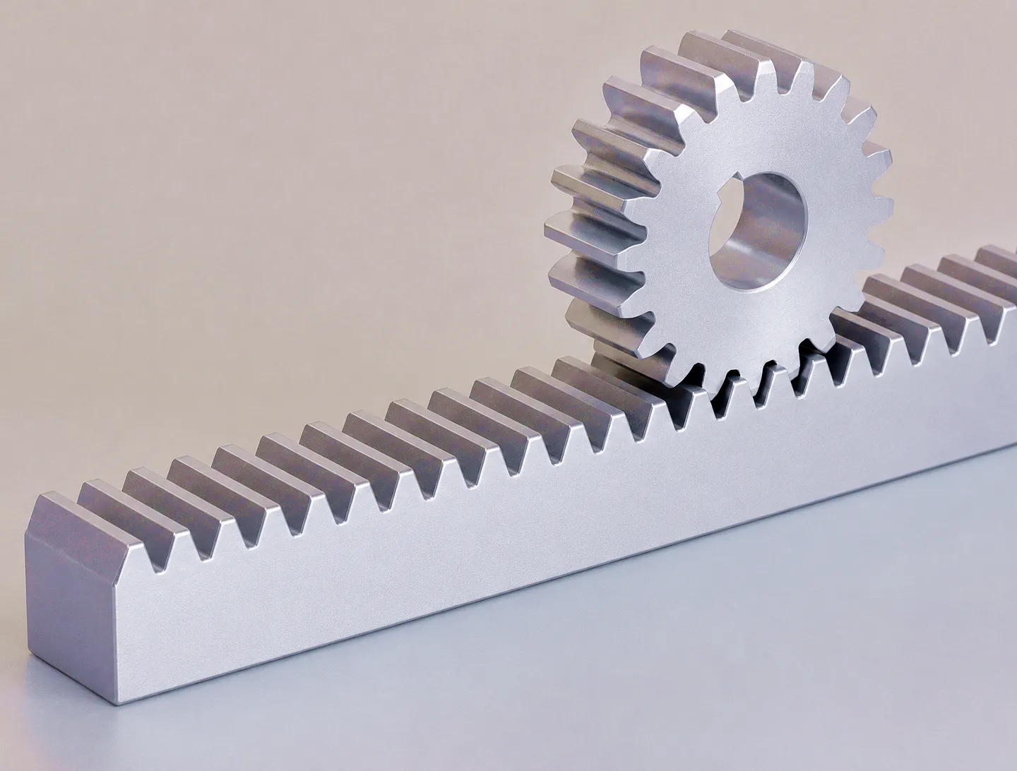 A gear rack functions as a gear with an infinite pitch circle radius — imagine unwrapping a large spur gear until the circular arc of its teeth becomes a perfectly straight line. When a pinion (a small circular gear) engages with this rack and rotates, the meshing teeth push the rack along a linear path. The velocity of linear translation is directly proportional to the pinion’s rotational speed and its pitch diameter, described by the relationship: linear velocity = angular velocity × pitch circle radius. This is not a mere textbook formula; it is the governing equation that engineers use to specify motor speeds, gear ratios, and encoder resolutions in every servo-driven axis that runs a gear rack.
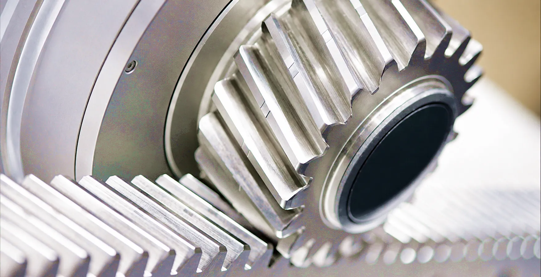
The involute tooth profile is critical here. Unlike simpler triangular or trapezoidal profiles, the involute geometry ensures that the contact ratio between rack and pinion remains constant regardless of minor centre-distance variations. This is what gives rack-and-pinion systems their characteristic smoothness and repeatability. In helical variants, the teeth are cut at an angle relative to the rack’s long axis. This angularity means multiple teeth are simultaneously in contact at any given moment, distributing load more evenly, reducing noise, and dramatically increasing the maximum transmittable force. For applications in Birmingham’s machine tool sector or in automated guided vehicle systems used in large distribution centres, helical gear racks can provide the linear positioning accuracy of ±0.02 mm per metre that production managers rely on to maintain part tolerances.
Backlash management deserves special mention. In standard rack and pinion pairs, a small clearance exists between the flanks of meshing teeth to allow lubrication and thermal expansion. In precision applications — CNC plasma cutting tables, automated inspection gantries, medical imaging positioners — this clearance becomes a source of positioning error. Engineers address this through preloaded twin-pinion arrangements or by specifying zero backlash rack solutions that mechanically eliminate the clearance through spring-loaded or adjustment-screw tension between two meshing pinions on the same axis.
Material Selection: What a Gear Rack Is Made From and Why It Matters
The workhorse grade. Medium carbon content gives a good balance of strength and machinability. Commonly used for standard-duty racks in conveyor systems and basic positioning stages. Can be induction hardened for improved surface life.
Chromium-molybdenum alloy preferred for heavy-duty applications. After quenching and tempering, tensile strength exceeds 1,000 MPa. The core remains tough while the surface accepts a hard case. Ideal for crane travel racks, industrial robots, and high-cycle machinery common in Sheffield and Birmingham’s engineering sector.
Used where corrosion is a primary concern — food processing plants, pharmaceutical production lines, and washdown environments. SUS316 offers chloride resistance suitable for coastal installations and chemical processing facilities. Strength is lower than alloy steel, so module size is typically increased to compensate.
Nylon (PA66) and acetal (POM) racks are lightweight, self-lubricating, and electrically non-conductive. They are preferred in light-duty office automation, medical devices, and laboratory instruments. The absence of metal-to-metal contact eliminates the need for lubricant — a significant advantage in cleanroom environments.
Beyond the base material, surface treatment defines the operational life of a gear rack. Induction hardening creates a hard surface layer — typically HRC 52–60 — while leaving the core at HRC 28–35 for shock resistance. Nitriding offers an alternative route: the process diffuses nitrogen into the steel surface at moderate temperatures, producing a compound layer of exceptional wear resistance without dimensional distortion. For corrosive environments, zinc phosphating followed by a lubricant coating provides interim protection during shipping and storage, while hard chrome plating or nickel plating offers longer-term corrosion defence without sacrificing dimensional precision. The induction hardened helical rack with surface treatment represents the current industry benchmark for balancing wear life against precision retention in high-duty-cycle automation.
Core Technical Advantages of Modern Gear Rack Systems
Unlike ball screws, which become impractical beyond three metres due to whip and resonance, gear racks can be joined end-to-end to cover theoretically unlimited travel lengths. Long-axis gantry systems used in steel fabrication yards in Middlesbrough routinely deploy racks spanning 20–40 metres with positional repeatability well under 0.05 mm.
Rack and pinion drives can operate at linear velocities exceeding 5 m/s while transmitting very large tangential forces. This combination of speed and force is unmatched by belt or lead-screw alternatives at comparable cost. In automated pallet transfer systems and fast-moving gantry cranes, this characteristic is commercially decisive.
The direct tooth engagement in a gear rack provides axial stiffness far superior to belt-driven systems. Where machining processes generate cutting forces that push back against the linear axis, a properly specified rack-and-pinion drive maintains position without springback — a critical characteristic for milling machines and laser cutting tables across the UK precision engineering supply chain.
A worn section of gear rack can be replaced independently without removing or re-engineering the entire linear axis. The pinion — the first component to show wear — is also easily swapped. For UK manufacturers operating under pressure to maintain Overall Equipment Effectiveness (OEE) targets, this localised replaceability translates directly into reduced planned maintenance windows.
Properly heat-treated steel gear racks remain dimensionally stable across a wide thermal range — typically -40°C to +200°C — making them suitable for foundry automation, outdoor rail-mounted systems exposed to British weather extremes, and cryogenic transport equipment without requiring special compensation mechanisms.
For travel distances above approximately 2 metres, rack and pinion drives often deliver a lower total installed cost than equivalent ball-screw systems, when factoring in support bearings, coupling hardware, and the screw itself. This economic advantage becomes even more pronounced at lengths above 4 metres — a common requirement in UK warehouse automation projects currently being rolled out across logistics hubs in the East Midlands and around Manchester.
Gear Rack Technical Specifications and Performance Parameters
The table below consolidates the principal technical parameters that procurement engineers and machine designers in the UK reference when specifying gear rack assemblies. Understanding these values is essential for correct sizing, supplier communication, and ensuring compliance with the mechanical design specifications of any given machine or structure.
| Parameter | Spur (Straight) Gear Rack | Helical Gear Rack | Zero-Backlash Rack |
|---|---|---|---|
| Module Range | M1 – M20 | M1 – M16 | M1 – M10 |
| Helix Angle | 0° (straight) | 14°, 19.5°, 20°, 45° | 0° or 20° (application-dependent) |
| Pressure Angle | 20° (DIN 867 standard) | 20° (normal) | 20° |
| Pitch Accuracy Class | DIN 6 – DIN 12 | DIN 5 – DIN 9 (ground: DIN 4–6) | DIN 4 – DIN 6 |
| Surface Hardness (HRC) | 28–35 (unhardened) / 52–60 (induction) | 52–60 (induction or case hardened) | 58–62 (precision ground after hardening) |
| Typical Material | C45, S45C, 1045 | 42CrMo4, SCM440 | 42CrMo4 (ground post-hardening) |
| Standard Length per Bar | 500 mm – 3,000 mm | 500 mm – 2,000 mm | 500 mm – 1,000 mm |
| Max Linear Speed | Up to 3 m/s (standard duty) | Up to 5 m/s (servo applications) | Up to 2 m/s (precision positioning) |
| Positional Accuracy (typical) | ±0.1 – ±0.3 mm/m | ±0.02 – ±0.05 mm/m (ground) | ±0.01 – ±0.02 mm/m |
| Backlash | 0.05 – 0.30 mm (depends on class) | 0.02 – 0.15 mm (precision ground) | <0.003 mm (preloaded arrangement) |
| Finish Options | Black oxide, zinc, natural | Induction hardened + ground, nitrided | Precision ground (Ra 0.4 – 0.8 µm) |
Industrial Application Scenarios: Where Gear Racks Are Deployed
The range of industries that rely on gear rack systems in the United Kingdom spans from century-old heavy manufacturing to cutting-edge automation. The following scenarios represent the principal deployment contexts, each demanding a different combination of rack specification, material grade, and surface treatment.
CNC machining centres, routing machines, and plasma cutting tables deploy helical gear racks on their X and Y axes to achieve high-speed linear motion with sub-millimetre accuracy. Sheffield’s advanced manufacturing zone and Birmingham’s precision engineering cluster both host machine tool integrators who specify DIN 5 or DIN 6 class precision ground helical racks mated with servo-driven pinions. The ground tooth surface finish (Ra ≤ 0.8 µm) is essential to achieve the repeatability demanded by aerospace and automotive tier-one suppliers in the region.
Heavy-duty portal cranes and transfer gantries operating at British port terminals along the Humber and at the Port of Tyne require gear racks capable of transmitting tens of thousands of newtons of force while maintaining positioning accuracy for automated container handling. 42CrMo4 induction-hardened racks with protective coatings are the standard choice, offering the combination of mechanical strength and corrosion resistance that North Sea coastal environments demand year-round.
The rack-and-pinion steering mechanism remains the dominant steering geometry in passenger vehicles. West Midlands automotive suppliers — many serving Jaguar Land Rover and Honda’s legacy supply networks — produce steering racks manufactured to extremely tight tooth-profile tolerances. The steering rack must transmit force predictably under varying lateral loads while exhibiting consistent feel across the full lock-to-lock range. Surface grinding of the rack teeth is mandatory at this quality tier.
Modern precision agriculture equipment deployed across East Anglia’s arable farmlands uses gear rack mechanisms to control seed drill depth, implement width adjustment, and headstock positioning on tractor-mounted implements. These racks must tolerate mud, moisture, and impact loading without loss of adjustment accuracy. Zinc-phosphated C45 racks with heavy greasing intervals are typical, with some premium manufacturers now transitioning to nitrided surfaces for extended service intervals between major field campaigns.
Automated Storage and Retrieval Systems (AS/RS) at distribution centres in the East Midlands — a region that hosts a disproportionate share of the UK’s logistics infrastructure — run aisle-captive stacker cranes on vertical gear rack masts. These vertical racks, typically running 8–15 metres high, must exhibit both high positioning accuracy and excellent fatigue strength, as duty cycles can exceed 200 cycles per hour in high-throughput e-commerce fulfilment operations running around the clock.
CT scanner gantry translation, MRI patient table drives, and surgical robot arm extension mechanisms all rely on miniature high-precision gear racks fabricated from stainless steel or non-magnetic alloys. In the biomedical manufacturing clusters around Cambridge and Oxford, demand for sub-10-micron positional accuracy and absolutely zero contamination makes plastic or stainless racks with ground surfaces the only acceptable option. The zero backlash rack configuration is frequently specified for robotic surgery platforms where any lost motion between command and execution is clinically unacceptable.
Sheffield Steel Fabrication Plant: Rebuilding a Plasma Gantry with Precision Helical Racks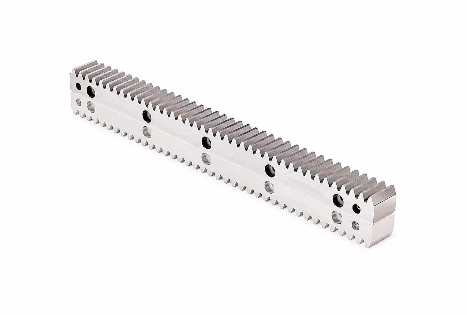
Hadley Steel Structures, a structural steel fabricator based in Sheffield’s Lower Don Valley, operates a fleet of large-format CNC plasma cutting tables used to process 6-metre and 12-metre structural steel sheets into precision-cut components for bridge, stadium, and industrial building frames. In early 2024, their most productive table — a 16-metre long dual-axis gantry — began exhibiting accumulated pitch error exceeding 0.8 mm per 10 metres of travel on the primary X axis. Detailed inspection revealed that the existing hobbed (non-ground) spur gear racks had worn unevenly due to inconsistent hardness distribution from the original supplier. The rack tooth flanks had lost their original involute geometry across three sections of the 16-metre axis, causing the CNC controller’s encoder to report positions that no longer corresponded with the plasma torch’s physical location. Cut-part dimensional errors were costing the plant roughly 12 tonnes of scrap steel per month.
The site engineering team contacted Ever Power through a UK-based industrial distributor in Leeds. After reviewing the existing axis geometry, motor specifications, and duty cycle data, Ever Power’s technical team recommended replacing the full 16-metre X axis with DIN 6 class M6 module 42CrMo4 induction-hardened helical gear racks, ground after hardening to Ra 0.8 µm. The helical tooth design increased the contact ratio compared with the original spur racks, reducing vibration during fast traverse moves and improving surface finish quality on cut edges. Custom mounting hole positions were confirmed against the existing bed mounting rail centres to eliminate any need for machine bed modification. The entire batch of eight rack bars — each 2 metres long, joined end-to-end — was dispatched from Ever Power’s facility with full material certificates, hardness test reports per bar, and dimensional inspection records conforming to the customer’s supplied inspection plan.
Post-installation verification using a laser interferometer on the rebuilt axis confirmed a pitch error of less than 0.04 mm per 10 metres — an improvement of more than 20:1 over the worn previous condition, and well inside the ±0.05 mm/m tolerance that Hadley’s quality procedures required. Monthly steel scrap from cutting errors dropped to less than 0.4 tonnes within the first production cycle, recovering the cost of the full rack replacement project within eight weeks of running production.
“The dimensional consistency across all eight rack bars was outstanding — our interferometer measurements matched Ever Power’s own inspection records within 0.005 mm. That level of repeatability from bar to bar is exactly what you need when joining sections end-to-end across a 16-metre gantry. We have not had a cutting error attributable to axis positioning in six months.”
“What impressed us most was the technical response time. We sent our axis drawings on a Tuesday afternoon, and Ever Power came back with a confirmed technical recommendation and delivery schedule by Wednesday morning. For a plant running three shifts with a downtime penalty clause, that turnaround makes a serious commercial difference.”
“We specified custom mounting hole positions to avoid re-drilling the machine bed, and every hole was within 0.1 mm of the drawing. The material certs and hardness reports included with the shipment satisfied our customer audit requirements immediately. Ever Power understands what UK manufacturers actually need from a supplier — documentation, accuracy, and no excuses.”
Frequently Asked Questions About Gear Racks
Related Products You May Need