Core Concept 01
What Is Module and Why Does It Govern Gear Rack Compatibility
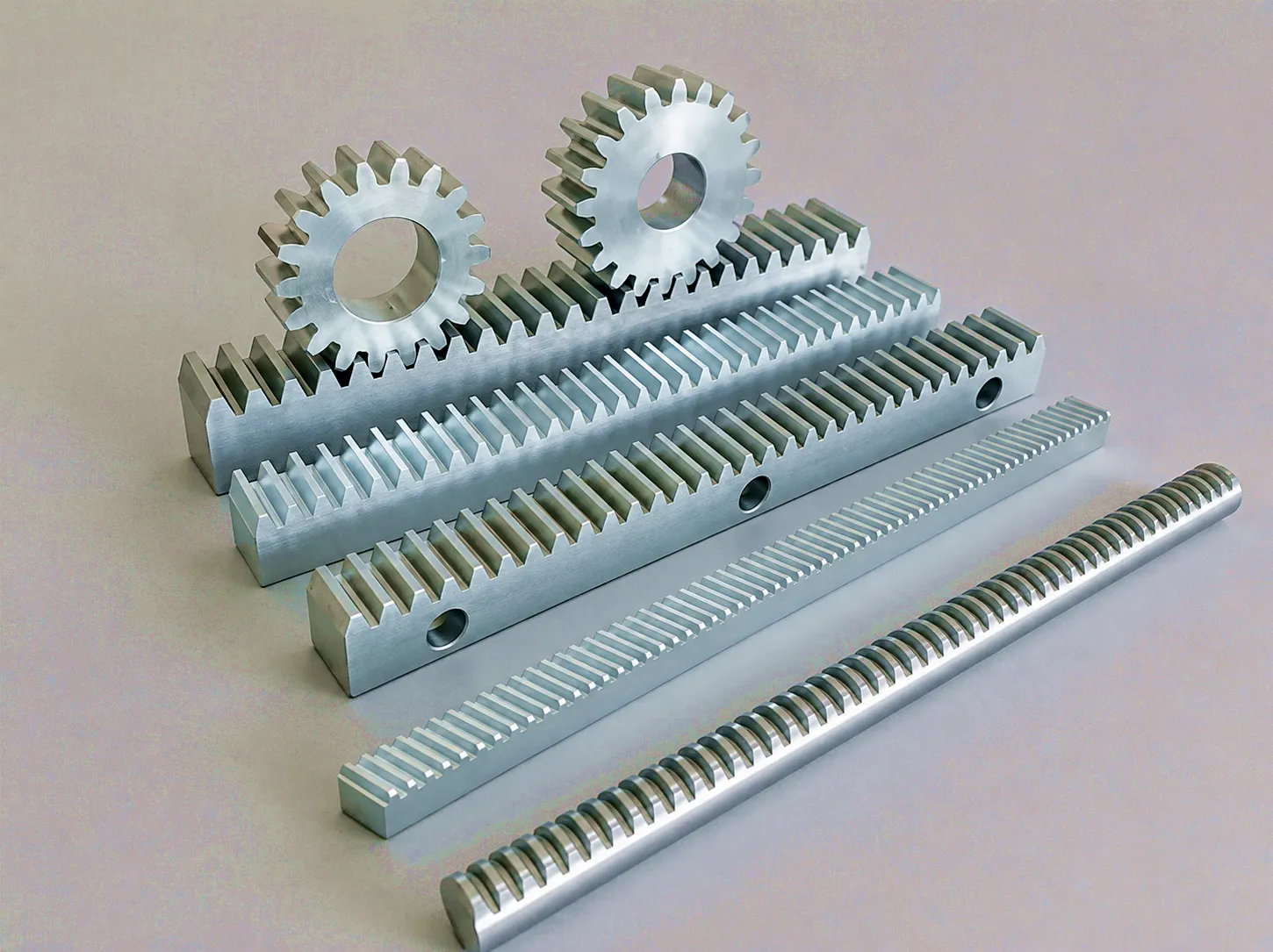
Module — abbreviated as m and measured in millimetres — is the most fundamental sizing parameter in metric gear design. It expresses the ratio of the reference circle diameter of a gear to its number of teeth: m = d / z, where d is the pitch circle diameter in millimetres and z is the tooth count. For a gear rack, which has an infinite pitch circle radius, module defines the tooth spacing in direct linear terms. A module 2 gear rack has a tooth pitch (the distance between corresponding points on adjacent teeth) of exactly 2π millimetres, or approximately 6.283 mm. Module 3 gives approximately 9.425 mm per tooth pitch, and so on.
The practical implication for UK buyers is absolute: a gear rack and its mating pinion must share the same module value. There is no adjustment, shimming, or workaround. Mixing module 2 rack with a module 3 pinion will result in violent meshing failure within moments of operation. When quoting or ordering, module should appear as the first dimensional parameter on every specification sheet — before tooth count, before length, before material grade.
Module standardisation follows ISO 54 and the equivalent BS 436 (British Standard for gears), which means that gear rack produced to these standards is fully interchangeable across different manufacturers — provided both the module and pressure angle match. For facilities in Manchester, Leeds, or Bristol procuring replacement rack for existing machinery, confirming the module is typically a matter of measuring two adjacent teeth with a vernier calliper and dividing the result by π. Many engineers carry a small module gauge set precisely because manual measurement on worn rack teeth can be ambiguous.
Higher module values mean physically larger teeth, which can transmit greater tangential forces along the rack face. A module 8 rack serving a heavy-duty gantry crane at a Teesside fabrication facility will look visually coarser than the module 1 rack on a precision metrological table — yet each is exactly correct for its application. Selecting module based solely on what “looks right” is a recurring procurement error; selection must flow from calculated tooth root bending stress and surface durability requirements, not visual impression.
Core Concept 02
Circular Pitch and Linear Pitch: Decoding the Numbers on Your Rack Datasheet
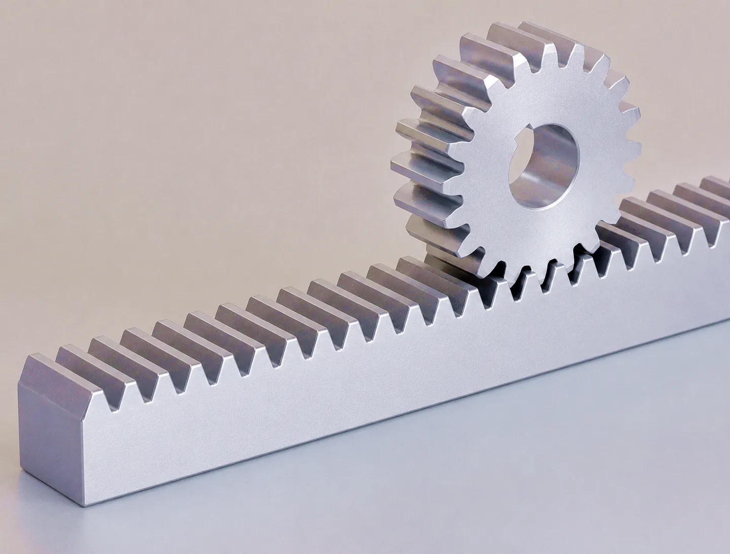
The arc length measured along the pitch circle between corresponding points on adjacent teeth. Expressed as p = π × m. For a rack, this becomes the linear distance between teeth measured along the pitch line.
An imperial measure equal to the number of teeth per inch of pitch circle diameter. DP and module are inversely related: DP = 25.4 / m. UK machinery built before full metrication may still specify rack in DP — conversion is essential before ordering metric replacements.
The tooth spacing measured along the base circle, equal to the circular pitch multiplied by the cosine of the pressure angle: pb = p × cos(α). This parameter governs the constancy of the transmission ratio during meshing, and is especially relevant in high-speed rack-and-pinion drive systems.
The pitch concept trips up many buyers in the UK because British engineering heritage contains a blend of imperial and metric tooling. Older machine tools manufactured in Coventry, Oldham, or Derby during the 1950s–1970s frequently used diametral pitch rack; the machinery has since been retrofitted, recontrolled, or simply continues in daily service. When a maintenance engineer orders a replacement rack segment for such a machine, confusing DP 8 (which is approximately metric module 3.175) with module 8 will result in a rack that looks superficially similar but will immediately destroy the pinion on first engagement.
The safest practice is to measure the actual tooth-to-tooth spacing with a micrometer screw gauge and compare it against both the metric pitch series (π, 1.5π, 2π, 3π mm per tooth) and the imperial DP series (3.175, 4.233, 6.350 mm per tooth for DP 8, 6, 4 respectively). A properly equipped supplier should be able to identify the standard from a caliper measurement alone. When evaluating a precision ground helical rack, the helix angle further modifies the apparent tooth spacing in the transverse plane — another layer of measurement complexity that an experienced technical team will navigate for you.
Core Concept 03
Pressure Angle in Gear Rack: Load Direction, Tooth Strength, and Why 20° Dominates
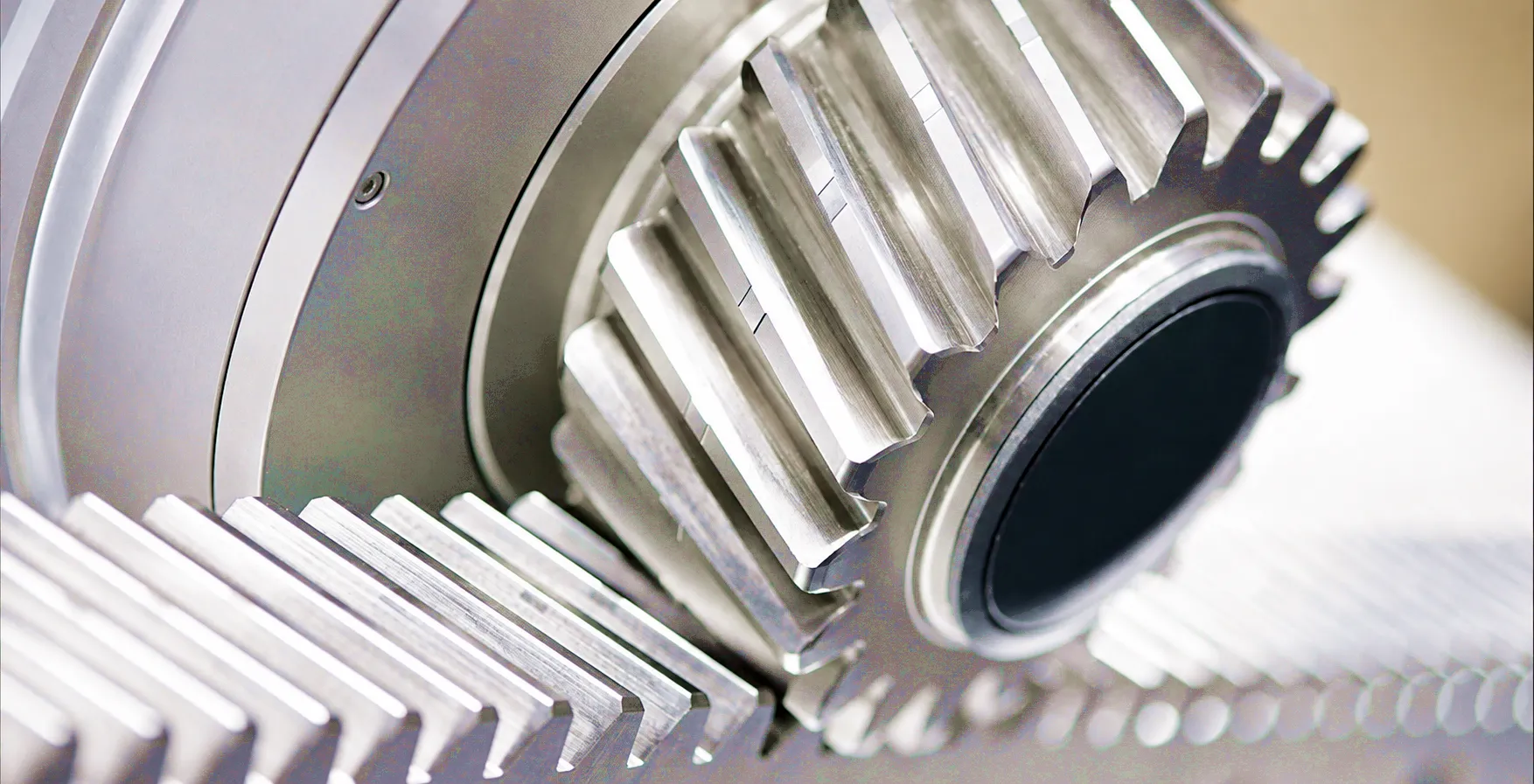
Pressure angle — denoted α — is the angle between the tooth force direction (the line of action or pressure line) and the tangent to the pitch circle at the point of contact. For a gear rack, it is more simply visualised as the angle between the tooth flank and a perpendicular to the rack pitch line. The two standard values in widespread global use are 14.5° and 20°, with 20° having become dominant across virtually all modern metric gear rack production, including the majority of stock held by UK distributors and imported directly from specialist manufacturers.
Pre-1960s
The 14.5° standard was rooted in the involute approximation of earlier cycloidal tooth forms. It produces shallower, slightly wider teeth with lower separating forces between rack and pinion — an advantage on lightly constructed or worn bearing arrangements. However, the tooth root is narrower relative to the tip, making it more vulnerable to bending fatigue under cyclic loads. Still encountered in older UK machine tool inventory and some US-origin equipment; any replacement rack for such machinery must match this pressure angle exactly.
Modern Practice
The 20° pressure angle delivers a broader, stronger tooth root profile and higher load-carrying capacity for a given module size. The greater separation force (radial component of the tooth load) demands more robust pinion bearing supports — but modern linear guides and bearing blocks handle this comfortably. Under ISO 54 and DIN 867, 20° is the default for all new gear rack design and manufacture. UK CNC router manufacturers, automation integrators, and materials-handling system builders overwhelmingly specify 20° rack as standard, and it should be your default unless engineering drawings explicitly state otherwise.
Critical note for mixed-fleet maintenance: Pressure angle mismatch produces the same catastrophic result as module mismatch — immediate, severe damage to both the rack teeth and the pinion on first engagement. Unlike a module error, which is often detectable by visual inspection of tooth size, a pressure angle mismatch on worn rack is essentially impossible to identify by eye and requires either a dedicated pressure angle gauge or comparison against a known-good specimen.
For facilities managing multiple machine generations — a common situation in the West Midlands and Yorkshire’s diverse manufacturing sectors — maintaining a clear equipment register that logs both module and pressure angle for every gear rack application will save considerable trouble at the next maintenance interval. Always confirm both parameters in writing when raising a quote request with any gear rack supplier.
Manufacturing Materials: What Your Gear Rack Is Made From and Why It Matters
Material selection directly impacts load rating, surface durability, environmental resistance, and ultimately the total cost of ownership.
Medium-carbon steel (equivalent to BS970 070M46) is the most widely used gear rack material for general industrial duty. Combines good machinability with adequate strength. Typically surface hardened to HRC 45–55 to resist tooth wear while retaining a tough core. Cost-effective for the majority of automation, conveyor, and positioning applications where contact stresses are moderate.
Chromium-manganese-titanium case-hardening steel used where high fatigue resistance is paramount. After carburising and quenching, the case hardness can reach HRC 58–62, while the core remains tough at HRC 30–40. Selected for gear rack in high-cycle servo drive systems, packaging machinery, and precision transfer lines where tooth bending and pitting fatigue govern design life.
Austenitic stainless grades offer excellent corrosion resistance for food processing, pharmaceutical manufacturing, and marine environments — all significant UK sectors. Lower hardness limits than carbon steel grades mean stainless gear rack is suited to moderate loads and reduced speeds. The hygienically cleanable surface and resistance to process chemicals make it the default specification for food-grade linear motion in facilities governed by BRC food safety standards.
Polymer gear racks — typically nylon PA66 or acetal POM-C — address applications requiring noise attenuation, self-lubrication, and resistance to non-metallic chemical environments. Widely used in healthcare equipment, light-duty automated guided vehicles, and cleanroom transfer systems. Tooth strength is considerably lower than metal rack, so module and application loading must be carefully verified. Offer significant weight savings in mobile or weight-sensitive assemblies.
Product Technical and Performance Specification Table
Reference data for standard gear rack supplied by Ever Power. Custom specifications are available; contact our engineering team for tailored solutions.
| Parameter | Straight Rack | Helical Rack | Ground Precision Rack | Induction Hardened Rack |
|---|---|---|---|---|
| Module Range | m1 – m12 | m1 – m10 | m1 – m6 | m3 – m12 |
| Pressure Angle | 14.5° / 20° | 20° | 20° | 20° |
| Tooth Profile | Involute, straight | Involute, helical | Ground involute | Ground / hobbed |
| Surface Hardness | HRC 45–55 | HRC 48–58 | HRC 55–62 | HRC 54–60 |
| Accuracy Grade (DIN) | DIN 8–10 | DIN 6–8 | DIN 4–6 | DIN 6–8 |
| Standard Length | 500 / 1000 mm | 500 / 1000 mm | 500 / 1000 mm | 1000 / 2000 mm |
| Typical Material | 45# Steel / C45 | 20CrMnTi / 42CrMo | 42CrMo4 / GCr15 | 45# / 42CrMo |
| Max Linear Speed | Up to 1.5 m/s | Up to 3 m/s | Up to 5 m/s | Up to 2.5 m/s |
| Noise Level | Moderate | Low | Very Low | Low |
| Typical Applications | General automation | CNC, servo drives | High-speed precision | Heavy-duty lifting |
Core Technical Advantages That Set High-Quality Gear Rack Apart
Understanding what differentiates a properly engineered gear rack from a basic commodity part is essential for specifying components in demanding UK industrial environments.
Gear rack teeth produced by profile grinding achieve DIN 4–6 accuracy, with tooth pitch errors below ±5 µm over a 300 mm span. This level of geometric precision is essential for servo positioning systems where accumulated pitch error directly translates into positional inaccuracy at the end effector. Ground rack eliminates the periodic velocity ripple (“DTE” — dynamic transmission error) that would otherwise generate vibration and noise in high-speed drive trains serving CNC machines, laser cutters, and automated storage and retrieval systems.
Selective induction hardening of gear rack teeth raises surface hardness to HRC 54–60 while leaving the core at HRC 28–35 — the ideal combination of wear resistance and impact toughness. Compared to through-hardening, induction treatment produces minimal distortion, so the pitch accuracy of the rack is preserved after heat treatment. The induction hardened helical rack with surface treatment is particularly suited to applications involving intermittent heavy loading, such as hydraulic press transfer systems and heavy gantry drives in Yorkshire’s steel processing sector.
In bidirectional positioning drives, backlash between rack and pinion creates a dead zone in motion reversal that degrades positioning repeatability. Zero-backlash rack configurations — achieved through precision ground flanks, preloaded twin-pinion arrangements, or anti-backlash pinion systems — eliminate this error source. Achievable positional repeatability of ±0.005 mm on well-aligned rack-and-pinion systems makes this approach competitive with ball-screw drives at longer travel lengths, and increasingly preferred for machine tool applications and large-format additive manufacturing gantries.
A helical gear rack — in which the teeth are cut at an angle (typically 15°–25°) relative to the rack axis — offers several performance advantages over a straight-tooth equivalent. The angled cut means multiple teeth are in contact simultaneously, distributing load more evenly and reducing per-tooth stress. This translates to smoother running, lower noise, and higher permissible tangential forces for a given module. The trade-off is an axial force component that must be reacted by the pinion bearings — a design consideration that is straightforward to accommodate in most servo drive assemblies.
Industrial Application Scenarios for Gear Rack in UK Manufacturing
From precision workshops in Derby to heavy fabrication yards in Tyneside, gear rack drives appear across an enormous breadth of UK industrial activity.
Large-format CNC routers, plasma cutters, and waterjet cutting tables that are commonplace in Birmingham’s sheet metal fabrication industry and across the South Wales engineering corridor rely on gear rack for their gantry axis drives. Travel lengths of 2 m to 8 m are standard; ball screws become impractical beyond roughly 3 m due to whip and manufacturing cost. Precision ground helical rack, paired with a pre-tensioned twin-pinion drive, delivers the bidirectional repeatability required for tight part tolerances without the weight and complexity of alternative linear drives. Module 2–3, DIN grade 5–6, with anti-corrosion coating for open environments.
Automated storage and retrieval systems (AS/RS) in UK distribution centres and manufacturing warehouses — particularly the expanding logistics infrastructure around the M1/M6 corridors in the East Midlands — use heavy-duty gear rack on their mast and carriage drives. Rack modules of 6–10 are typical for loads above 1,000 kg, with rack mounted vertically or horizontally depending on axis configuration. Induction hardened rack on 45# steel ensures the wear life needed for 24/7 operation with duty cycles that would rapidly exhaust softer materials. Ground joining surfaces on rack segments allow precise end-to-end butting for continuous travel paths without position discontinuities.
The automotive and off-highway vehicle sector — with a significant UK manufacturing base in Coventry, Derby, and the surrounding Midlands — uses gear rack as the central element of rack-and-pinion steering. The rack translates rotation of the steering column (via the pinion) into linear movement of the track rod ends, which steer the wheels. Design parameters here are driven by packaging envelope, fatigue life requirements, and the feel characteristics required at the steering wheel. Ground rack with tight tooth profile tolerances is essential for consistent steering ratio and road feel — poor rack quality directly degrades driver confidence and NVH (noise, vibration, harshness) performance.
London’s West End theatre district and major touring stage productions make extensive use of gear rack mechanisms for set piece drives, flying systems, and motorised scenery wagons. The requirements here differ substantially from industrial applications: low noise is paramount, the rack must be mechanically safe under mains power loss, and the aesthetic requirement may demand concealment within structural elements. Stainless steel rack, with food-grade lubrication, is also used on mobile bar and catering equipment serving UK events and exhibitions. Module 2–4, stainless or nickel-plated carbon steel, with self-locking pinion arrangements for vertical safety.
UK Network Rail and its supply chain use gear rack in a variety of specialist maintenance vehicles and trackside equipment. Rack drives power the working platforms on overhead line equipment (OLE) maintenance trains, position ballast cleaning and tamping heads, and actuate crossing mechanisms on some automated maintenance platforms. The stringent safety certification required (typically to EN 13001 for crane-like machinery) demands full traceability of rack material heat treatment data, dimensional inspection records, and batch identification — requirements that serious gear rack suppliers must be able to meet routinely through documented manufacturing quality systems.
Gear rack mechanisms appear in precision agricultural equipment — including seed drill depth controls, sprayer boom positioning arms, and harvester header height adjustment systems — manufactured by companies serving UK arable and dairy operations across East Anglia, Lincolnshire, and the Scottish Borders. The outdoor environment demands robust corrosion protection, typically zinc phosphating plus paint or zinc-nickel plating. Module 3–6 in this application space, often in ductile iron for severe duty and cost-effective high-volume production. IP rating of the drive assembly and rack surface treatment are co-specified to match soil, chemical, and moisture exposure in the field.
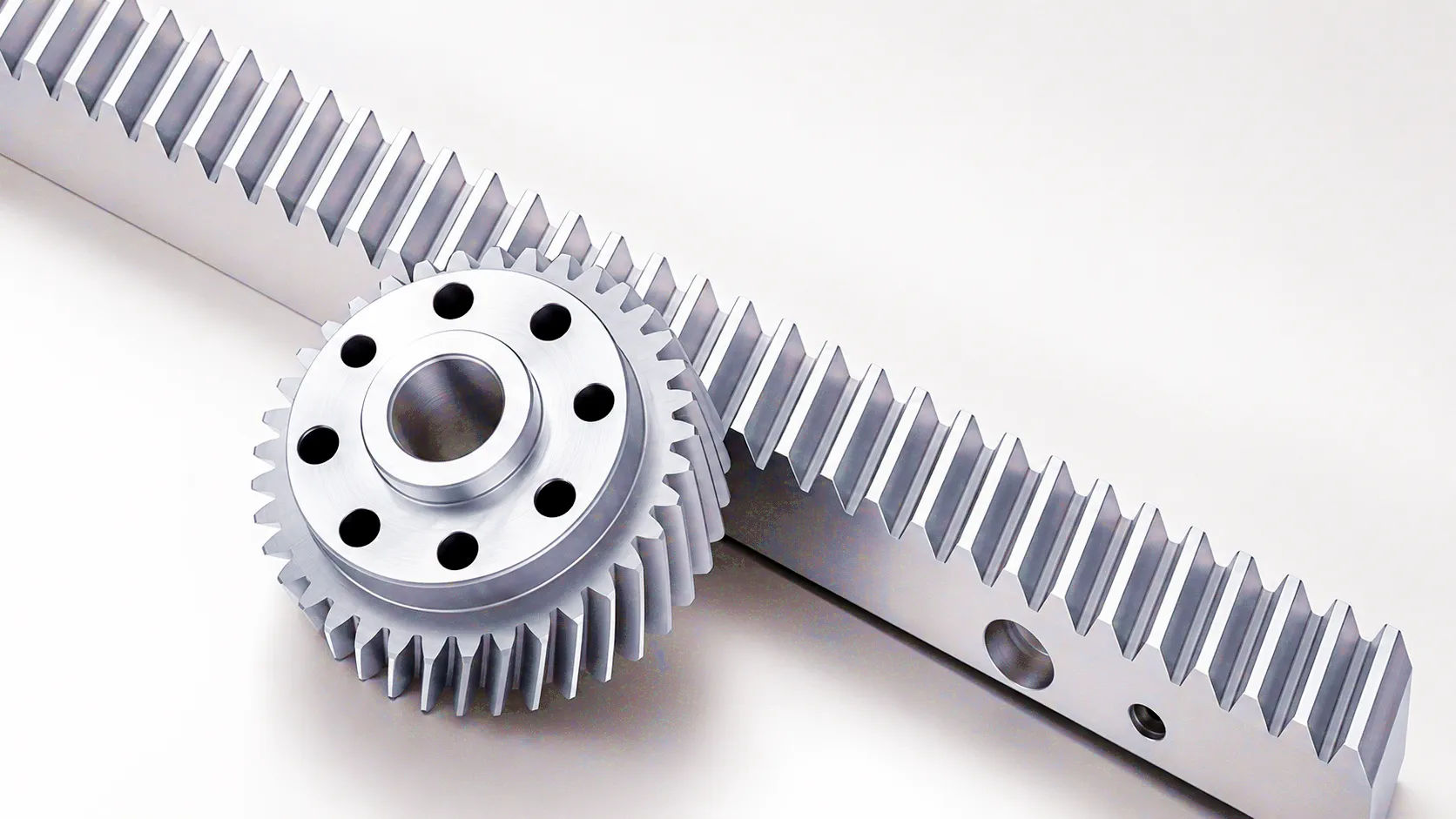
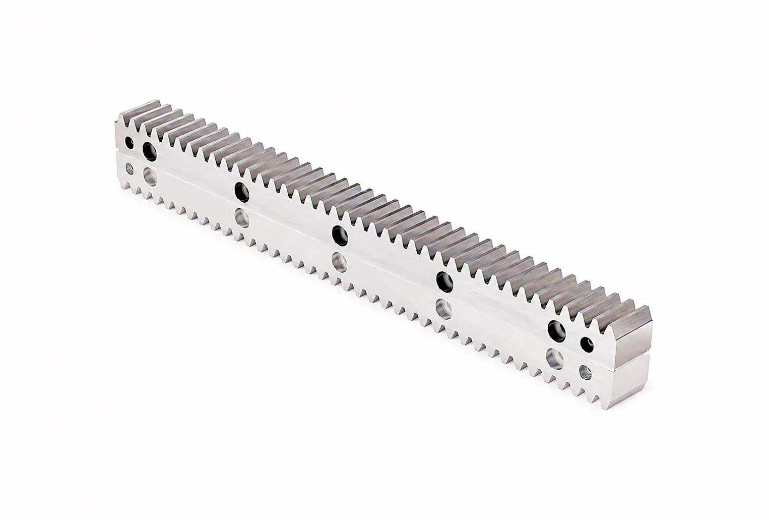
Sheffield Precision: How a Steel Component Manufacturer Eliminated Downtime with Ever Power Gear Rack
Hartley-Forde Engineering Ltd, a precision steel components manufacturer based in Sheffield’s Attercliffe industrial district, operates a fleet of five heavy-duty plasma cutting gantries that serve the structural steelwork and pressure vessel fabrication markets. In 2024, the company was experiencing increasing unplanned downtime on three of these machines, tracing back to accelerated tooth wear and pitting on the X-axis gear rack. The original rack — a DIN 8, module 4 straight rack in 45# steel without heat treatment — had been in continuous service for eleven years, but maintenance intervals were shortening. The combination of abrasive cutting dust, intermittent lubrication, and the sheer duty cycle was overwhelming the surface hardness of the unhardened rack. Each replacement shutdown cost an estimated £3,800 in lost production per day, and the original OEM rack supplier had a 14-week lead time for replacement sections.
Ever Power’s technical team worked directly with Hartley-Forde’s maintenance engineer to assess the application. Module, pressure angle, and mounting configuration were confirmed from a sample section sent for measurement. Rather than a like-for-like replacement, Ever Power proposed upgrading to induction hardened module 4 rack in 42CrMo steel, with a case hardness of HRC 56 and DIN grade 7 accuracy — one grade tighter than the original. The upgrade required no mechanical changes to the machine, as the tooth geometry (module, pressure angle) remained identical. Ever Power supplied the full complement of five machines’ rack requirements — totalling 84 metres of finished rack — within four weeks, including material certification, hardness test reports, and pitch accuracy inspection data for each rack segment. Mounting face and drill hole positions were customised to match Hartley-Forde’s existing track mounting arrangement exactly, avoiding any modification work on site.
What UK Customers Say About Ever Power Gear Rack
“The induction hardened rack Ever Power supplied has been running on our large-format CNC plasma cutter for nearly a year without any measurable wear. The tooth pitch accuracy across the full 12-metre travel was spot-on — our servo drive’s following error didn’t change at all after fitting the new rack. The material certificates and CMM data they supplied were exactly what our quality department needed. We wouldn’t go back to our old supplier.”
“We source helical rack from Ever Power for our automated transfer line build projects. The customisation flexibility is what sets them apart — we needed a module 3 rack with non-standard mounting holes and a specific centre distance tolerance, and their engineering team turned around a prototype in three weeks. The helical rack runs significantly quieter than the straight rack it replaced, which is a real advantage in our facility where noise is regulated. Excellent communication throughout the supply process.”
“We needed ground precision gear rack for a new coordinate measuring machine transfer system — DIN 5 minimum, with pitch error under 6 µm per 300 mm. I sent Ever Power a spec sheet and got a detailed technical response with their proposed solution within 24 hours, including sample data from a previous comparable batch. Delivery was 18 working days from order. The rack went in, and our positional accuracy was exactly as calculated. For precision applications, this is the level of supplier you need.”
Explore the Ever Power Gear Rack Product Range
Select the product that matches your application or speak to our team for a bespoke recommendation. Engineers in Manchester, Leeds, Glasgow, and London can reach us directly at sales@farm-equipment-parts.com.
Frequently Asked Questions About Gear Rack Selection and Sourcing in the UK
Measure the distance across two complete tooth pitches with a vernier calliper or micrometer, then divide by 2π (approximately 6.283). The result should closely match a standard module value from the series: 1, 1.25, 1.5, 2, 2.5, 3, 4, 5, 6, 8, 10. If the result is closer to a value in the series 3.175, 4.233, 6.350 (millimetres per tooth), the rack is likely imperial diametral pitch (DP 8, 6, or 4 respectively) rather than metric module. For precise identification, send a sample section to Ever Power and we will confirm module, pressure angle, and accuracy grade from the physical part.
Precision ground helical gear rack pricing varies considerably with module size, accuracy grade, length, material, and surface treatment. As a broad guide, a 1,000 mm length of module 3 ground helical rack in DIN grade 6, 42CrMo4 steel, with standard coating, sits in the range of £85–£180 depending on quantity and specification. Induction hardened variants command a premium of 25–40% over equivalent unhardened stock. Standard ex-stock items typically ship within 5–10 working days from Ever Power; custom specifications typically require 3–6 weeks depending on complexity and order volume. For a firm quote tailored to your specific module, accuracy, and length requirements, contact us at sales@farm-equipment-parts.com with your full specification.
For high-speed servo positioning in automotive manufacturing — where travel speeds commonly reach 2–5 m/s and positioning repeatability of ±0.01 mm or better is expected — the correct specification is precision ground helical rack at DIN 5 or better, in 42CrMo4 with case hardening to HRC 55+. Helical teeth reduce dynamic transmission error and noise, which is particularly beneficial in facilities where servo drives operate at high frequency. The helical rack should be paired with a preloaded, backlash-compensated pinion. Zero-backlash rack-and-pinion configurations are increasingly the preferred choice for new robot track and gantry installations across the Midlands automotive supply chain.
UK buyers sourcing gear rack for safety-critical applications — crane drives, railway maintenance equipment, and pressure vessel handling — should look for suppliers who can provide: full material traceability (mill certificates per EN 10204 3.1 or 3.2), hardness test reports for each batch, dimensional inspection data from calibrated CMM equipment, and ISO 9001 certified quality management. Ever Power provides all of these as standard for applicable products. Buyers in Sheffield, Leeds, and Newcastle working on heavy industrial projects regularly procure from us directly by emailing sales@farm-equipment-parts.com with their full specification and certification requirements. Quotes are typically returned within 24 hours on working days.
Yes — pressure angle directly determines which pinion you must use, and the two values are not interchangeable. A 20° pressure angle rack produces a stronger tooth root and higher load capacity, but requires a 20° pressure angle pinion. A 14.5° rack requires a 14.5° pinion. Mixing them causes immediate destructive contact and typically damages both parts within seconds of first engagement. The 20° standard is now universal for all new metric gear rack design under ISO 54, so if you are replacing rack on modern equipment, 20° is virtually certain to be correct. Only on machinery manufactured before the 1960s — particularly UK-built machine tools from the era of the old BS gear standards — is 14.5° likely to be specified. When in doubt, measure or consult a specialist supplier before ordering.
For a custom gear rack quote, the most efficient approach is to email sales@farm-equipment-parts.com with a simple drawing or dimensioned sketch (even a hand sketch scanned to PDF is fine) showing: the required module and pressure angle, total rack length, cross-section dimensions, mounting hole positions and thread sizes, required accuracy grade (DIN class), desired material and surface hardness, and any surface treatment requirements. Our engineering team will confirm the specification, flag any feasibility issues, and return a detailed quotation typically within one working day. For Manchester-based retrofit projects, we can also arrange to collect a sample of the existing rack via courier if specification identification is needed before quoting.
Ready to Specify Your Gear Rack?
Send your module, pressure angle, accuracy grade, and length requirements to Ever Power. Our engineering team responds within 24 hours, Monday to Friday, and custom specifications are our speciality.
sales@farm-equipment-parts.com | Ever Power Industrial Transmission | Supplying UK B2B customers