Understanding Fatigue Failure in Gear Racks: Why Material Matters More Than Geometry
Every engagement cycle introduces a bending moment at the tooth root — the narrowest cross-section where stress concentrates most severely. Steels with higher core strength and finer grain structure resist crack initiation at this critical zone. In gear racks used on CNC machining centres across Sheffield’s precision engineering sector, tooth root fatigue accounts for the majority of premature replacements.
At the tooth flank, repeated Hertzian contact stresses drive subsurface crack nucleation, leading to pitting, spalling, and micro-pitting over time. The material’s hardness profile — particularly the depth and consistency of the hardened case versus the tough core — governs how well a gear rack withstands this surface fatigue. Induction-hardened alloy steels consistently outperform through-hardened carbon steels in this respect.
Micro-motion between tooth flanks under oscillating loads generates fretting debris and initiates surface cracks in materials with insufficient hardness or poor tribological properties. This mode is particularly problematic in gear racks used in reciprocating portal cranes and gantry systems in UK dockyard facilities like those around Southampton and Teesside, where cycles are short but highly frequent.
The interplay between these three fatigue mechanisms means material selection cannot be reduced to simply choosing the hardest available steel. Engineers must balance hardness, toughness, ductility, and hardenability depth — a combination that only specific alloy compositions and heat treatment sequences can reliably deliver. The gear rack’s module, pressure angle, and tooth profile all feed into the stress calculations, but without an adequately specified raw material, no geometric optimisation can compensate.
Core Material Options: How Steel Grade Determines Fatigue Performance
Medium-carbon steel. The entry-level workhorse for standard-duty gear racks. Through-hardened to ~200–240 HB, it delivers acceptable bending strength for moderate-load applications such as sliding door systems and light agricultural conveyors. Fatigue limit in bending: approximately 290–310 MPa. Hardenability is limited, making it unsuitable for large cross-sections where through-hardening is required.
Chromium-molybdenum alloy steel. The most widely specified material for precision gear rack applications in UK industry. Excellent hardenability allows consistent hardness profiles at greater cross-sectional depths. Quenched and tempered to 280–320 HB; induction-hardened flanks can reach 55–60 HRC at the surface with a tough core retained beneath. Fatigue limit in bending: 420–470 MPa — a significant step up from C45.
Case-hardening grade with manganese-chromium alloying. The preferred material for gear racks requiring very high surface hardness alongside excellent core toughness. Gas-carburised to produce a case depth of 0.8–1.5 mm at 60–62 HRC, with a core retaining 35–40 HRC. This dual hardness profile maximises resistance to both surface pitting and tooth root fracture — the ideal material for servo-driven linear axes and high-cycle packaging machinery.
Austenitic stainless grades. Used exclusively where corrosion resistance overrides load capacity requirements — pharmaceutical conveying systems, food-processing lines, and coastal installations. Fatigue limits are lower (typically 180–220 MPa in bending), and these grades cannot be hardened by heat treatment. They are specified for gear racks in wet environments throughout UK food manufacturing facilities in the East Midlands, where cleanliness standards are paramount.
What separates a mediocre gear rack from a high-performance one is rarely the tooth profile — it is almost always the cleanliness of the steel billet and the consistency of the heat treatment. UK-specification gear racks supplied to Tier 1 automotive plants around Birmingham and Coventry routinely call for ESR (electroslag remelted) or VAR (vacuum arc remelted) quality billets, which dramatically reduce non-metallic inclusions that act as crack initiation sites. A standard commercial-quality 42CrMo4 billet can contain oxide and sulphide inclusions that reduce fatigue strength by 15–25% compared with ESR-grade bar. For gear rack applications in safety-critical rail infrastructure or aerospace ground support, this distinction is non-negotiable.
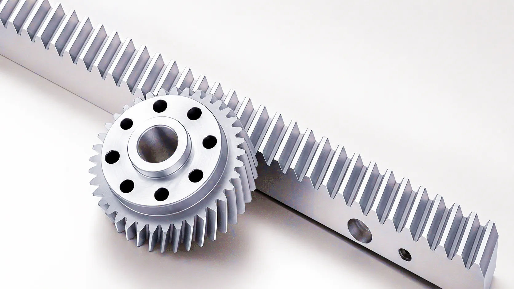
The interaction between material cleanliness, alloy composition, and subsequent thermal processing defines the fatigue performance ceiling of any gear rack. A well-designed helical rack tooth profile — such as those found in Ever Power’s Precision Ground Helical Rack range — can only realise its potential when the underlying material has been correctly specified and verified through incoming inspection protocols including hardness mapping and ultrasonic testing.
Heat Treatment Pathways and Their Fatigue Strength Outcomes
The heat treatment route applied to a gear rack billet is, in many ways, as critical as the alloy grade itself. It is through thermal processing that the raw potential of an alloy steel is converted into a specific hardness profile, residual stress distribution, and microstructural state — all of which directly determine fatigue resistance. The four principal routes used in gear rack production are:
Post-treatment grinding is a subject that deserves particular attention in the context of fatigue. While grinding restores tight dimensional tolerances after heat treatment-induced distortion, aggressive grinding can introduce tensile residual stresses at the tooth surface — the opposite of the compressive stresses that induction hardening is specifically designed to create. Thermal damage from grinding, sometimes called “grinding burn,” can reduce the fatigue strength of an induction-hardened gear rack tooth by 20–30% if wheel selection, infeed rates, and coolant application are not carefully controlled. UK manufacturers operating to BS EN ISO 6336 standards are increasingly mandating Barkhausen noise inspection or nital etch checks on finished gear rack flanks as part of their incoming goods inspection protocol.
Gear Rack Technical Performance Parameter Table
The table below summarises key technical parameters across the principal gear rack material and treatment combinations. These values represent typical performance benchmarks for precision-manufactured components and should be used as a guide during specification — final values depend on specific alloy heat, bar size, heat treatment batch parameters, and post-processing sequence.
| Material / Grade | Heat Treatment | Surface Hardness | Core Hardness | Bending Fatigue Limit (MPa) | Contact Fatigue Limit (MPa) | Typical Module Range | Typical Application |
|---|---|---|---|---|---|---|---|
| C45 / EN8 | Through-hardened | 200–240 HB | 200–240 HB | 290–310 | 550–620 | M1–M10 | Light conveyors, gates, agricultural |
| 42CrMo4 / EN19 | Q+T only | 280–320 HB | 280–320 HB | 370–420 | 720–800 | M2–M16 | General industrial, automation |
| 42CrMo4 / EN19 | Induction hardened | 55–60 HRC | 28–34 HRC | 420–470 | 1050–1200 | M2–M20 | CNC axes, servo-driven linear motion |
| 20MnCr5 / EN36 | Gas carburised + Q | 60–62 HRC | 35–42 HRC | 490–540 | 1300–1500 | M1–M8 | High-speed packaging, aerospace tooling |
| 31CrMoV9 | Gas nitrided | 700–900 HV | 30–36 HRC | 380–430 | 900–1050 | M0.5–M4 | Precision metrology, semiconductor |
| SUS316 / 304 | Annealed / solution | 160–200 HB | 160–200 HB | 180–220 | 400–480 | M1–M6 | Food processing, pharma, coastal |
Industrial Application Scenarios Across UK Manufacturing
Sheffield’s precision engineering heritage demands gear racks capable of sustaining 50–100 million positioning cycles without measurable pitch deviation. Linear axes on five-axis machining centres use precision-ground helical gear racks in module M3–M6 with induction-hardened 42CrMo4, achieving positional repeatability within ±0.01 mm over 3-metre travel distances. Material cleanliness is verified via ultrasonic C-scan before rack production begins.
Transfer lines in Birmingham’s automotive assembly plants use gear racks to drive welding jig positioning carriages. These applications demand gear rack fatigue strength capable of handling combined dynamic loads from carriage inertia and weld gun reaction forces — typically 15–25 kN at cycle rates of 6–12 strokes per minute, over a production lifetime of 15 years. Induction-hardened helical gear racks in M6–M10 are standard.
Heavy industrial crane systems along Teesside’s steel and chemical processing corridor require gear racks for end-carriage rack-and-pinion drives. These applications see gear racks carrying wheel loads of 80–250 kN over rail spans up to 50 metres. Through-hardened or induction-hardened C45 and 42CrMo4 gear racks in M20–M40 are used, with mounting holes drilled to DIN 5480 tolerances for direct bolted installation onto crane girder flanges.
Stainless steel gear racks in SUS304 or SUS316L are the only acceptable choice for washdown-intensive food production environments. The East Midlands hosts numerous large-scale dairy and bakery operations where conveyor indexing systems use stainless gear racks with plastic-coated mating pinions to eliminate lubricant contamination risk. Fatigue loads are modest, but the corrosion environment without adequate material selection would cause rapid degradation.
Bristol’s aerospace cluster — anchored around Rolls-Royce, Airbus UK, and their supply chains — uses gear racks in jig and fixture positioning systems where traceability of raw material is mandatory. Material certs to EN 10204 3.1 standard, heat treatment certificates, and hardness survey documentation are all required before delivery acceptance. Carburised 20MnCr5 gear racks with case depths verified by metallographic cross-section are commonly specified for the highest-duty positioning axes.
Network Rail-approved gear rack actuator systems for point machines and crossing operators use through-hardened and case-hardened gear racks to withstand the high-impact, low-frequency loading characteristic of rail switch operation. Each actuation cycle involves rapid load application and reversal — a fatigue regime that demands materials with high fracture toughness alongside surface hardness. Special corrosion-resistant coatings are applied over the hardened steel body to suit the UK’s wet climate conditions.
Core Technical Advantages of Precision Gear Rack Systems
Unlike many mechanical components where failure is difficult to predict, gear rack fatigue performance can be calculated with high confidence using ISO 6336 or AGMA 2101 stress analysis methods, provided the material properties are accurately characterised and consistent. This allows maintenance engineers at UK facilities to implement predictive replacement schedules based on actual load histories, avoiding both premature replacement and unexpected downtime.
Properly specified helical gear racks offer stiffness values of 350–600 N/mm per mm of rack length in typical module M4–M8 configurations, enabling very compact drive designs. The helical tooth form distributes contact load across a longer tooth flank than equivalent spur racks, reducing peak Hertzian stress and extending fatigue life. For UK system integrators working within tight machine footprints, this load density is a decisive advantage.
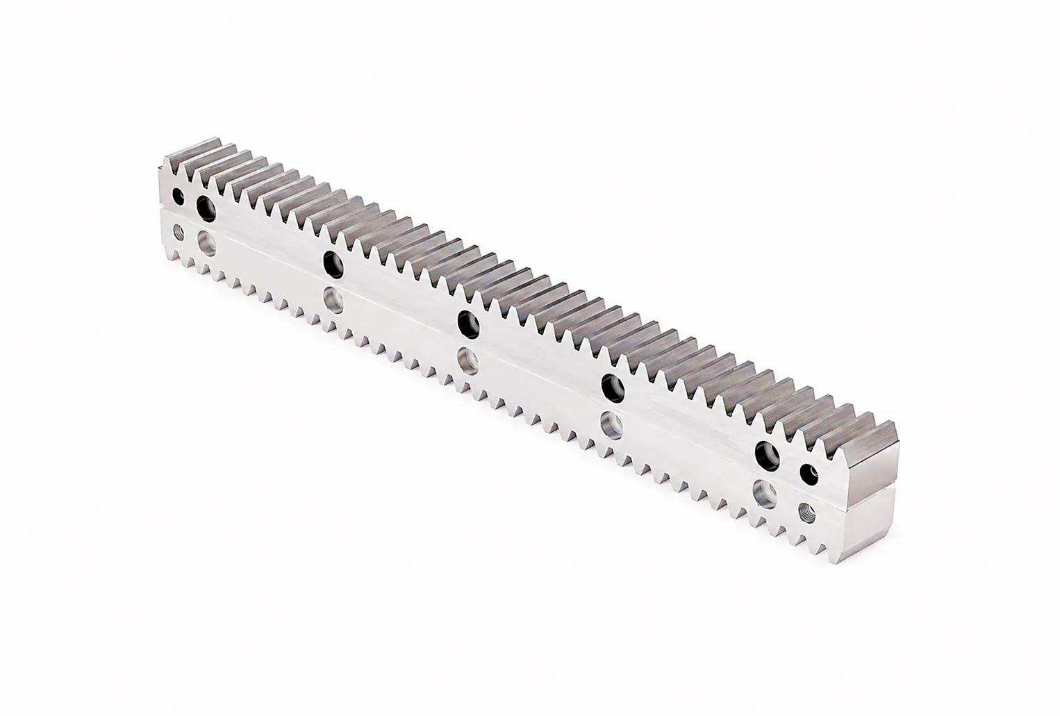
Ground gear rack sections can be butted end-to-end with precision joint machining to achieve effectively unlimited travel lengths, making them the default solution for large-format gantry systems in UK logistics warehouses, automated storage and retrieval systems, and long-travel laser cutting machines. Pitch continuity at the joint is maintained to within 0.005 mm on premium-grade ground sections, ensuring consistent dynamic performance across the full travel range. See our Zero Backlash Rack range for precision-joining applications.
Ground helical gear racks operating at pitch line velocities up to 3 m/s generate significantly lower noise levels than comparable milled spur racks — a meaningful operational consideration in UK manufacturing facilities where the Working at Height and COSHH regulations intersect with noise exposure limits under the Control of Noise at Work Regulations 2005. Measured noise reductions of 8–12 dB(A) compared with milled rack solutions have been documented in controlled trials.
Ever Power: Precision Gear Rack Manufacturing and Custom Specification Services
Ever Power operates a vertically integrated gear rack manufacturing facility equipped with CNC gear hobbing centres, CNC grinding lines dedicated to rack production, and in-house induction hardening cells with real-time power monitoring. Our quality system is certified to ISO 9001:2015 and our hardness testing, CMM dimensional verification, and surface roughness measurement capabilities ensure every gear rack leaving our facility meets or exceeds the specification agreed with the customer. From prototype single-piece samples through to volume production runs of several hundred metres of precision ground gear rack per month, our supply chain is structured to serve the demanding requirements of UK engineering customers reliably and on schedule.
Our customisation capabilities extend across every dimension of gear rack design. Material grade selection, module specification, pressure angle, tooth geometry (spur or helical), helix angle, rack cross-section profile (rectangular, T-section, or customer-defined), mounting hole patterns, end machining features, and surface treatment options — including zinc phosphate, black oxide, and specialty coatings for corrosive environments — are all routinely handled by our applications engineering team. UK customers benefit from our experience supplying into the same industrial sectors they serve, and from our export logistics capability enabling 7–14 day delivery of standard catalogue items to mainland UK addresses.
Customer Success Story: Automated Storage System Retrofit, Leeds
Frequently Asked Questions About Gear Rack Material Selection and Fatigue Performance
Talk to Ever Power’s applications engineering team. We supply precision gear racks to UK manufacturing and OEM customers with full material certification, custom dimensions, and competitive lead times.