
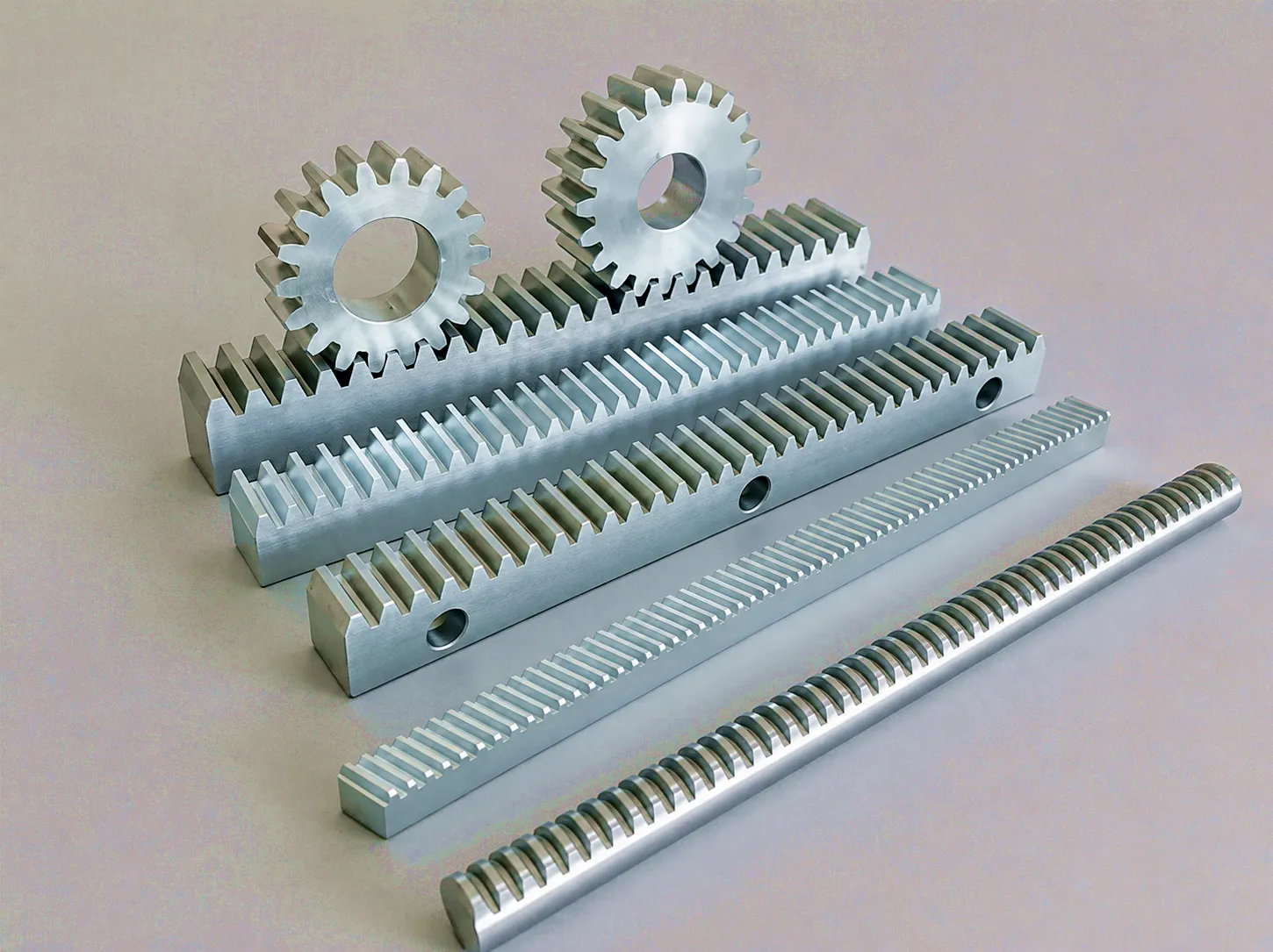
The Mechanical Principle Behind Gear Rack Motion
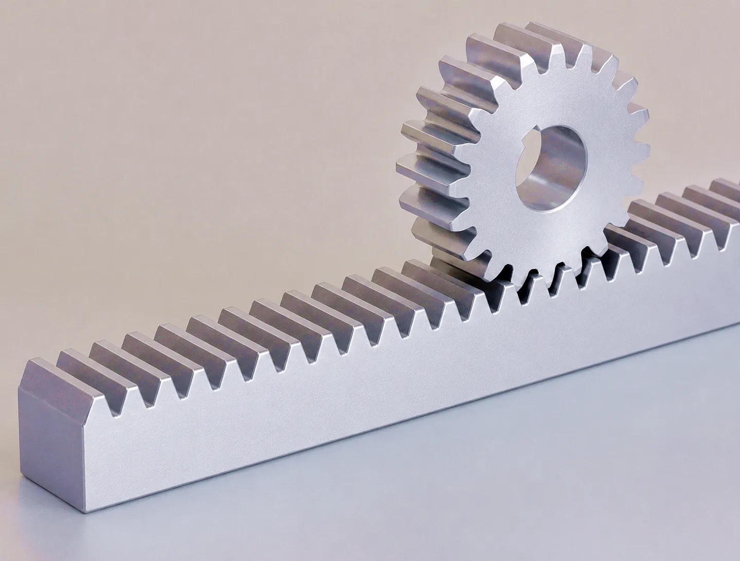
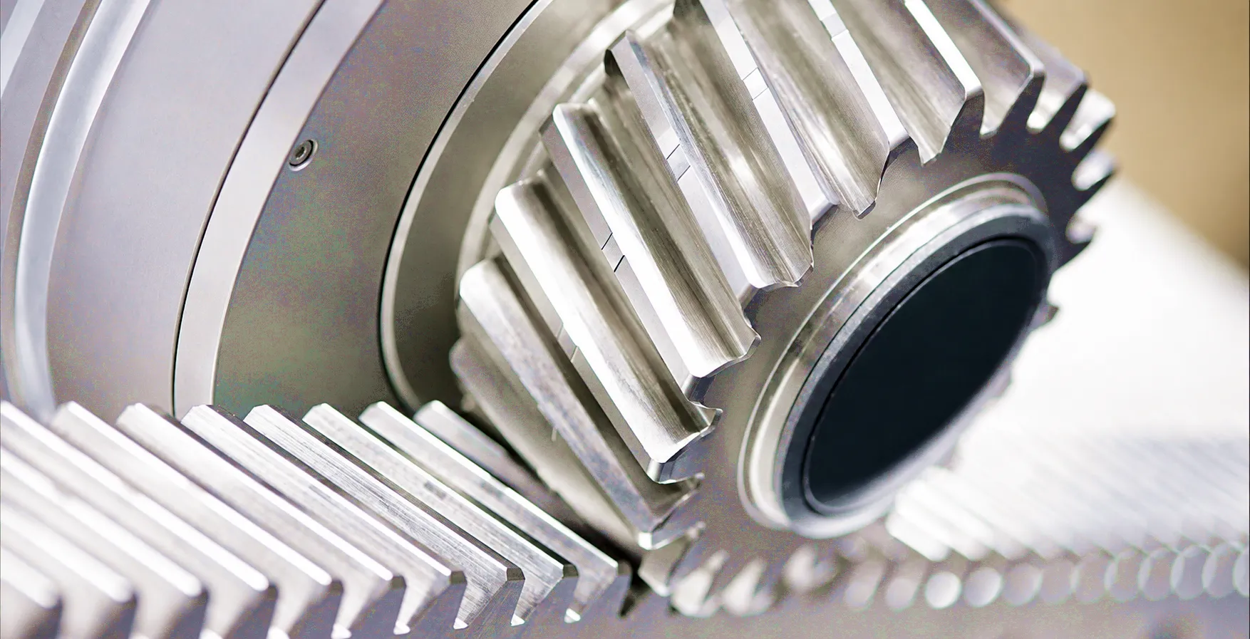
A gear rack is, at its core, a spur or helical gear with an infinite pitch circle radius — its teeth are arranged in a straight line rather than around a circumference. When a cylindrical pinion rotates against this rack, each tooth of the pinion successively engages a tooth of the rack, pushing the rack (or itself, if the rack is fixed) along the linear axis. The fundamental law of gearing — that the common normal at the contact point must pass through the pitch point — dictates how the two profiles must be shaped. For an involute tooth profile, this holds true across a range of centre distances, which is why involute gears tolerate small mounting errors without catastrophic transmission error. But that same geometric tolerance window is also the space in which backlash lives.
When the pinion drives the rack in one direction, the driving flanks of the pinion teeth push against the driven flanks of the rack teeth. No gap exists on the driving side. But on the non-driving side — the trailing flanks — there is a deliberate clearance. This clearance is backlash. It is introduced intentionally during manufacturing because perfectly zero clearance would cause the teeth to bind as thermal expansion, lubrication film thickness, and elastic deflection all vary. In a straight-tooth rack, backlash is purely linear, measured along the pitch line. In a helical rack, the helical overlap distributes tooth engagement across a longer contact line, which tends to reduce the effective play felt at the carriage, but the root cause remains the same: the gap between non-driving flanks at the pitch cylinder.
Root Causes: Where Backlash Enters the System
Every rack tooth is cut or ground to a nominal tooth thickness with an allowable deviation. DIN 3962 / ISO 1328 define tolerance grades from IT3 (ultra-precision ground) to IT12 (rough cut). A DIN 8 rack may have a tooth thickness deviation of up to ±0.07 mm per module. Multiply this across both the rack tooth and the mating pinion tooth and the total tolerance stack on the mesh gap can reach 0.14 mm per module — before any mounting error is added. For high-speed CNC routing tables common in UK sheet-metal shops, even half this plays out as visible tool-path deviation at the workpiece edge.
The centre distance between the pinion axis and the rack pitch line is the most sensitive single variable governing backlash magnitude. An increase of just 0.05 mm in centre distance translates, for a module-3 involute pair with a 20-degree pressure angle, to approximately 0.037 mm of additional backlash at the pitch line. This relationship is approximately linear and is given by the formula: backlash increase = 2 × delta-c × tan(pressure angle). In practice, centre distance variation comes from bearing wear, thermal growth of the machine structure, improper shimming of the pinion mount, and — in long rack runs such as those found on portal gantry machines in Sheffield aerospace cells — differential thermal expansion along the rack bed itself.
A rack is typically assembled from multiple sections joined end to end. Each section has an individual pitch tolerance and a cumulative pitch error over its length. When two sections butt together on a machine bed, the joint becomes the worst-case location for pitch error: the accumulated error of the outgoing section adds to the first-tooth error of the incoming section. British machinery manufacturers joining 1-metre rack sections across a 5-metre axis can see a cumulative pitch error of 0.05 to 0.15 mm at the joint, depending on rack grade. This manifests as a brief spike in backlash and in transmission error, which servo drives detect as a velocity disturbance.
New racks run with their as-manufactured backlash. In service, abrasive wear — driven by contamination, inadequate lubrication, or excessive contact stress — removes material from the tooth flanks and the addendum radius. Because the pinion typically rotates far more often than any single point of the rack traverses the full rack length, pinion teeth wear at a higher rate. The result is a progressive increase in backlash over service life. In UK food manufacturing and packaging environments, where water wash-down limits lubrication options, induction-hardened racks and pinions are favoured precisely because their hardened surface layer resists this wear mode over long maintenance intervals.
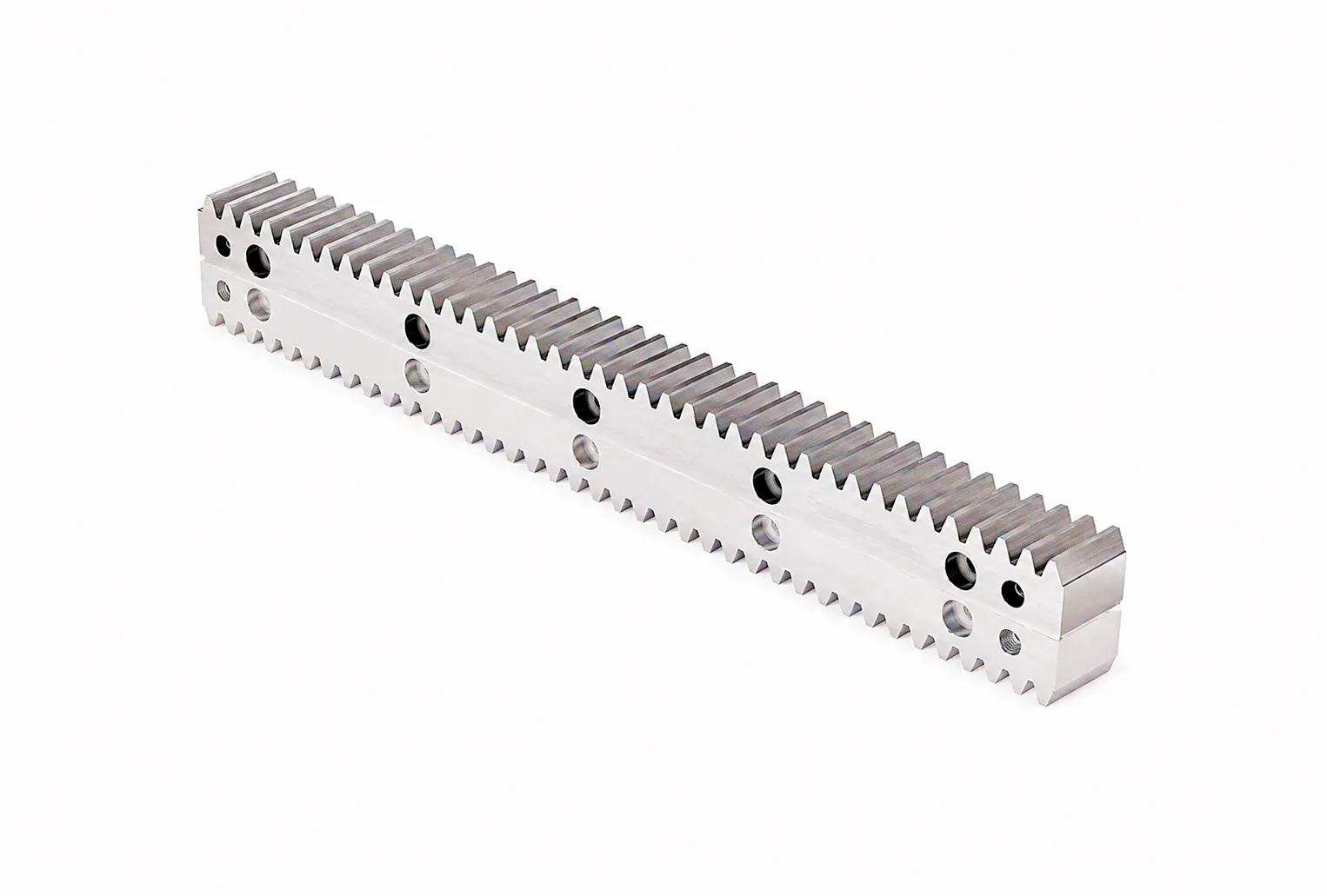
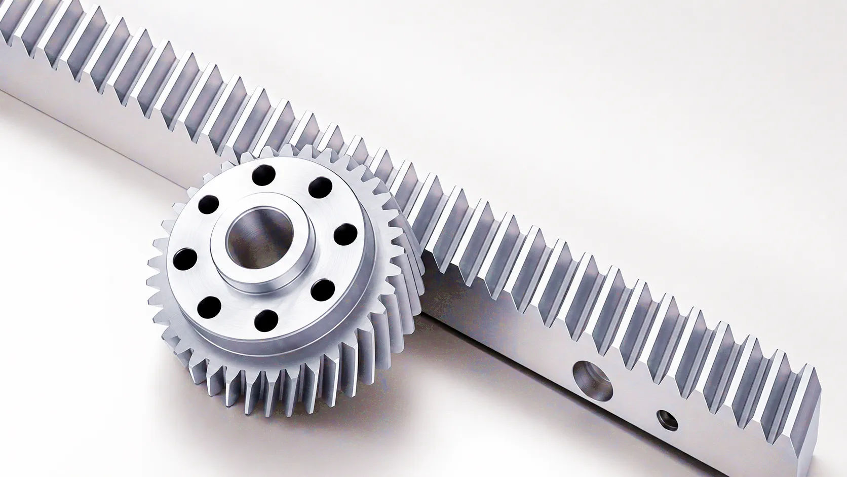
Core Materials and How They Influence Backlash Behaviour
The workhorse material for general-purpose gear racks worldwide. C45 (equivalent to British Standard EN8) offers a good balance of machinability, tensile strength (around 600–800 MPa after normalising), and cost. When used in hobbed or milled form without subsequent heat treatment, C45 racks are well-suited to moderate-duty conveyor drives, positioning slides, and agricultural implement lift mechanisms. Because the tooth flanks remain at roughly 200 HB surface hardness, wear rate under lubricated conditions is moderate and backlash growth over a multi-year service life is predictable and manageable through periodic shim adjustment of the pinion mount.
For applications demanding high load density and wear resistance — such as the long-travel axes of heavy-duty plasma and waterjet cutting tables found extensively in Midlands fabrication shops — 42CrMo4 (EN19 equivalent) is the preferred base material. After profile grinding to DIN 4–6 quality, the rack undergoes induction hardening, which brings the tooth flank surface to 58–62 HRC while leaving the core tough at 280–320 HB. The benefit for backlash management is direct: a hard tooth surface resists the micro-ploughing wear that progressively widens the tooth gap. An induction hardened helical rack with surface treatment maintains its as-manufactured backlash specification far longer than an unhardened equivalent, reducing re-calibration frequency and associated production downtime.
At the highest end of the accuracy spectrum, precision ground helical racks manufactured to DIN 6 or better represent the current state of the art for machine tool builders, semiconductor handling, and medical device manufacturing. The grinding operation follows heat treatment, removing the distortion introduced by the heat cycle and restoring tooth profile, pitch, and surface roughness to the tight tolerance band required. A precision ground helical rack can achieve a cumulative pitch error of under 0.012 mm per 300 mm of travel and a tooth profile deviation below 0.006 mm — figures that directly translate into sub-10-micron positioning repeatability when combined with an appropriate zero-backlash pinion assembly and a closed-loop servo drive.
Certain niche environments — pharmaceutical clean rooms, coastal marine installations, and hygienic food handling lines — require corrosion resistance that carbon steel cannot provide without special coatings. Stainless steel (typically 316 or 17-4 PH) gear racks offer excellent chemical resistance at the cost of slightly lower hardness and, therefore, modestly faster wear under high-contact loads. Polymer composites such as nylon-reinforced acetal provide a self-lubricating alternative for light-duty positioning mechanisms, with the additional benefit that any wear tends to be gradual and audible, giving maintenance teams early warning of increasing backlash before it affects part quality.
Product Technical and Performance Parameters
Core Technical Advantages of Low-Backlash Gear Rack Systems
A zero-backlash gear rack drive holds its commanded position on direction reversal without the deadband that characterises conventional rack-and-pinion systems. For CNC machining centres and laser cutting tables — both widely deployed across the East Midlands engineering corridor — this translates directly to tighter dimensional tolerances on finished parts.
By eliminating the free angular travel through the mesh, stiffened and preloaded rack drives respond to servo commands with far greater immediacy. This is particularly valuable in pick-and-place automation and gantry robots where acceleration and deceleration cycles happen many hundreds of times per shift — a scenario common in UK automotive component assembly plants in the West Midlands.
Induction-hardened and profile-ground rack flanks resist micro-pitting and abrasive wear over tens of millions of pinion cycles. The consequence is a predictably long and flat backlash growth curve: the as-manufactured backlash specification remains valid for a substantial fraction of the design life, reducing unscheduled maintenance interventions and the associated production loss.
Helical rack geometry distributes contact load across a longer flank area, which reduces surface temperature rise at the mesh and moderates the thermal growth that would otherwise translate into effective backlash variation during a production run. Combining a helical rack with a temperature-compensated pitch ensures the drive maintains its specified play across a meaningful operating temperature window.
Unlike ball-screw drives, which become impractical beyond roughly 4–6 metres of travel due to whip and critical speed limitations, gear rack drives extend cleanly to 20 metres or more using precision-jointed rack sections. Properly matched cumulative pitch error at joints maintains positioning accuracy across the full travel — making this format the dominant choice for large-format router beds, bridge cranes, and rail-guided transfer systems in UK heavy industry.
Modern rack drive designs accommodate dual-pinion preload arrangements — two pinions on the same axis, spring or hydraulically loaded against each other in opposite tooth flanks of the rack — that reduce net backlash to near zero without relying solely on tight manufacturing tolerances. This is a systems approach to backlash management that complements rather than replaces precision rack quality.
Industrial Application Scenarios: Where Backlash Control Defines Performance
In multi-axis machining centres — the backbone of precision engineering clusters in Birmingham and Coventry — the X and Y axis drives must reverse direction thousands of times per component cycle. Any backlash at the rack mesh appears as a contour error at the cutting tool, degrading surface finish and dimensional accuracy. For this reason, machine tool builders specify rack quality at DIN 5 or better and pair it with preloaded dual-pinion assemblies. The servo drive’s backlash compensation algorithm, while useful as a secondary measure, cannot substitute for mechanically minimised play at the source.
Large-format cutting tables serving the structural steel and plate fabrication sectors — heavily represented across South Yorkshire and Teesside — drive their long gantry axes with rack-and-pinion systems because the travel requirements (6 to 20 metres) rule out ball screws. Here, backlash matters in a slightly different way: the carriage velocity at direction reversal determines kerf width consistency. A system with 0.2 mm of backlash will produce a measurable kink in a contoured profile cut because the cutter continues to traverse while the motion axis reverses through the dead zone. Selecting an induction-hardened rack rated for the duty cycle, alongside a software acceleration profile that avoids abrupt reversals, is the standard engineering solution used by leading UK fabricators.
Distribution warehousing and pallet-based AS/RS installations — a sector that has expanded rapidly in the UK’s logistics corridor running through the East Midlands — depend on rack-driven stacker cranes that must stop accurately at bin locations without over-travel. The rack drive sees many millions of low-to-medium speed reversals over a service life of 10 to 20 years. Moderate-grade, induction-hardened straight racks are the norm here: precision-ground quality is not needed because the positioning encoder closes the loop, but hardened flanks are essential to limit backlash growth to a level the control can compensate across the entire service life.
Motorised rack drives on site hoists, glazing lifts, and formwork jacking systems in the UK construction sector face a very different set of demands: load reversal under gravity loading, exposure to rain, grit, and temperature swings characteristic of British outdoor working conditions, and infrequent but safety-critical operation. Here, the rack’s role is structural as much as kinematic — it must transmit the rated load safely even with worn flanks. Quality-grade C45 racks with appropriate tooth module and pitch circle diameter, paired with self-lubricating pinion housings, are standard specification on compliant UK construction hoists certified to EN 12159.
Clean-room dispensing robots, tablet press feed systems, and medical imaging positioners require backlash levels typically below 0.015 mm to maintain dosing accuracy and image registration. This application class draws on precision-ground stainless steel racks or polymer composite racks, combined with spring-preloaded pinion cassettes that maintain constant mesh pressure as thermal conditions vary within the equipment housing. UK pharmaceutical manufacturers operating under MHRA guidelines specify these systems through a validated qualification process that includes documented backlash measurement before and after accelerated life testing — an approach that demands supplier traceability from raw material to finished tooth form.
Measuring and Verifying Backlash in Assembled Systems
Quantifying backlash in a rack drive is straightforward in principle but requires careful methodology in practice. The most direct method uses a dial test indicator (DTI) mounted on the driven carriage, with the drive locked in one direction. The carriage is then pushed manually in the opposite direction — loading the non-driving tooth flanks — and the DTI deflection before the motor begins to resist movement is the functional backlash at that position. Repeating this measurement at multiple points along the rack travel reveals whether backlash is uniform (indicating good pitch consistency) or position-dependent (indicating local pitch error, a bent rack, or an out-of-true guide rail).
For higher accuracy measurement — particularly relevant when qualifying a machine to ISO 10791-3 for machining centres — a laser interferometer or calibrated linear encoder replaces the DTI. The control system commands a reversal, and the difference between the commanded position and the measured position at the instant of first movement defines the backlash as seen by the motion controller. This approach captures not only the gear mesh gap but also the contribution of guide way compliance, coupling backlash, and servo following error — giving a complete picture of the drive train’s reversing behaviour. UK machine tool manufacturers subject to BS EN ISO standards use this method routinely during factory acceptance testing.
Customer Success Story: Sheffield Structural Steel Fabricator
A well-established structural steelwork fabricator operating a production facility on the outskirts of Sheffield — a city with a manufacturing heritage that runs through its identity as deeply as steel runs through its soil — contacted Ever Power in early 2024 following repeated quality complaints from their largest client, a UK rail infrastructure contractor. The fabricator’s primary plasma cutting gantry, a 14-metre travel machine built on a competitor’s rack and pinion system, was producing visible kinks and radius errors on curved cut profiles. The machine had been in service for seven years, and the original C45 straight rack had never been replaced.
Ever Power’s application engineer conducted a remote consultation, reviewing the machine’s servo drive error logs and a DTI measurement report provided by the fabricator’s maintenance team. The diagnosis was clear: backlash at the rack joint nearest to the home position had grown to 0.38 mm — nearly four times the original specification — due to seven years of continuous operation without lubrication top-up to the rack grease nipples. At the problematic joint, cumulative pitch error from the joint misalignment added a further 0.12 mm of position error on direction reversal.
Ever Power supplied a matched set of module-4 induction-hardened helical racks to DIN 6 quality, with pre-drilled and reamed mounting holes on a 20 mm pitch to match the existing machine bed. The rack sections were supplied with a matched joint preparation guide to ensure pitch continuity at the butt joints. Installation was completed by the fabricator’s own maintenance crew over a weekend, with commissioning support provided remotely by Ever Power’s technical team. Post-installation DTI measurement confirmed assembled backlash of 0.022 mm at all points along the travel. The rail infrastructure contractor’s profile tolerance requirement of ±0.5 mm was met with significant margin, quality complaints ceased, and the fabricator subsequently placed a standing order for rack replacement sets on a five-year cycle — a maintenance interval they validated against the wear rate data provided with the Ever Power rack inspection documentation.
“The dimensional conformance report that came with the rack set was exactly what our quality department needed to sign off the installation without an external inspection. The tooth pitch measurements were inside DIN 6 on every section — not just close. That level of documented accuracy from a supplier at this price point is genuinely unusual in our experience of the UK market.”
“We needed a non-standard helix angle to match our existing pinion — a detail that ruled out every UK distributor we approached. Ever Power’s engineer confirmed the geometry calculation the same afternoon and turned around a sample rack within three weeks. The fit was perfect, the induction-hardened surface has taken the load without any sign of pitting after six months, and the backlash is still within spec.”
“Delivery to our Coventry plant was on day 18 — ahead of the quoted 20 working days — and the packaging was designed around protecting the ground tooth surfaces during transit. Small details, but they tell you a lot about how seriously a supplier treats precision components. We have since standardised on Ever Power racks across all four of our gantry machines.”
Related Products for Complete Gear Rack Drive Systems
Engineered for applications where reversal accuracy is paramount — servo-driven axes with sub-10-micron positioning requirements.
DIN 4–6 ground quality, low noise, long contact line — the standard for machine tool X/Y axis drives.
58–62 HRC tooth flanks, long-travel cutting tables and gantry axes — wear resistance for multi-shift production environments.
Integrated V-guide geometry combines rack drive and linear guidance — reduces part count and eliminates guide-to-rack alignment error.
Frequently Asked Questions
Ready to eliminate backlash from your gear rack drive? Contact Ever Power for a technical consultation and custom quotation.
sales@farm-equipment-parts.com
edit by gzl