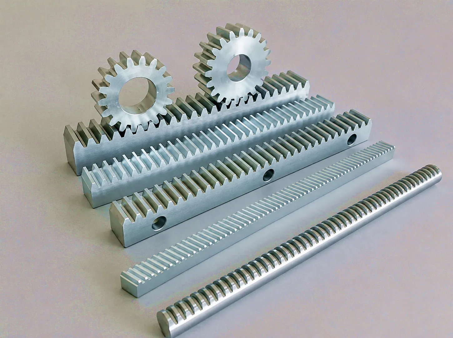
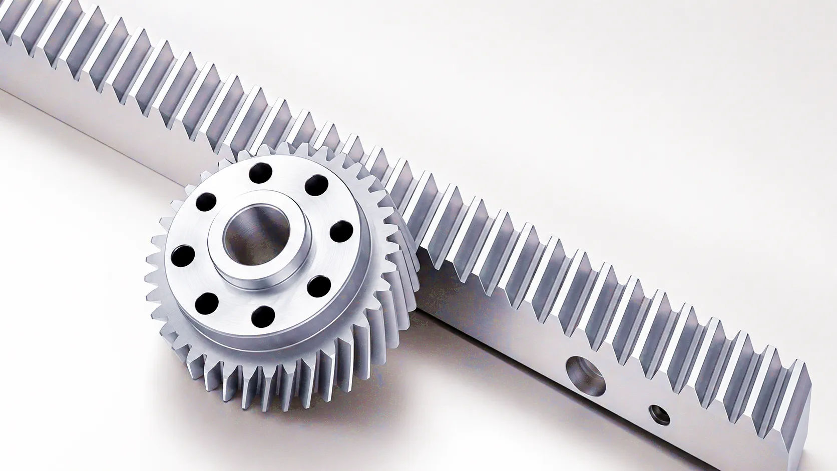
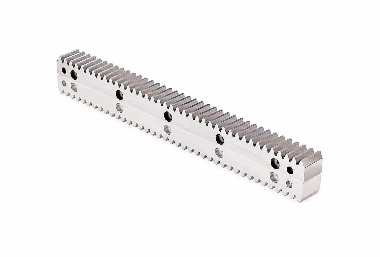
 The gear rack sits at the heart of countless linear motion systems — translating rotary input into precise straight-line movement with a reliability that no belt, chain, or leadscrew can quite match across long travel distances. Yet despite how widely gear racks appear in CNC machine tools, gantry systems, automated warehouse racking, and heavy portal cranes, comparatively few engineers have looked closely at how a gear rack is actually made. The manufacturing route — whether hobbing, peripheral milling, or precision surface grinding — determines everything from tooth profile accuracy and surface finish to load capacity and expected service life under high-cycle industrial duty. In the UK’s advanced manufacturing centres, from the precision engineering clusters around Sheffield and Birmingham to the aerospace supply chain in the North West, specifying the right rack starts with understanding what happens on the shop floor.
Hobbing: The Foundation of Volume Gear Rack Production
Hobbing is the most widely used process for cutting gear rack teeth at scale, and understanding it properly reveals why so many standard catalogue racks share similar accuracy grades regardless of brand. In hobbing, a multi-start helical cutting tool — the hob — rotates in a tightly controlled relationship with the workpiece. For a gear rack, the workpiece is a straight bar rather than a rotating blank, which means the hob traverses linearly along the rack’s length while both the hob and rack maintain a synchronised velocity ratio. This generating motion replicates the conjugate action of meshing gears in the cutting tool itself, producing involute tooth flanks through the envelope of successive hob tooth cuts rather than by copying a single cutting edge. The result is a theoretically correct involute profile at every tooth, produced at a cycle time that competing processes struggle to match for medium and long rack lengths.
For straight (spur) racks, the hob axis is set at the hob’s helix angle relative to the rack surface, typically between 2° and 5° for standard hobs. Helical racks require an additional compound axis tilt combining both the hob helix angle and the desired rack helix angle — commonly 14° or 20° for industrial helical gear racks — and this compound setting demands a high-quality machine tool with tight rotary axis stiffness to maintain consistent tooth lead across the full rack length. On modern CNC hobbing centres, in-process gauging can monitor pitch accumulation error in real time and apply compensating feed corrections, which is how leading manufacturers achieve DIN Class 7 or even Class 6 accuracy directly from the hobbing operation without subsequent grinding. Hobbing produces gear racks efficiently from C45 carbon steel, 42CrMo4 alloy steel, and stainless steel grades, and the process integrates naturally with post-hob induction hardening lines that selectively harden the tooth flanks and roots while leaving the rack body tough and ductile.
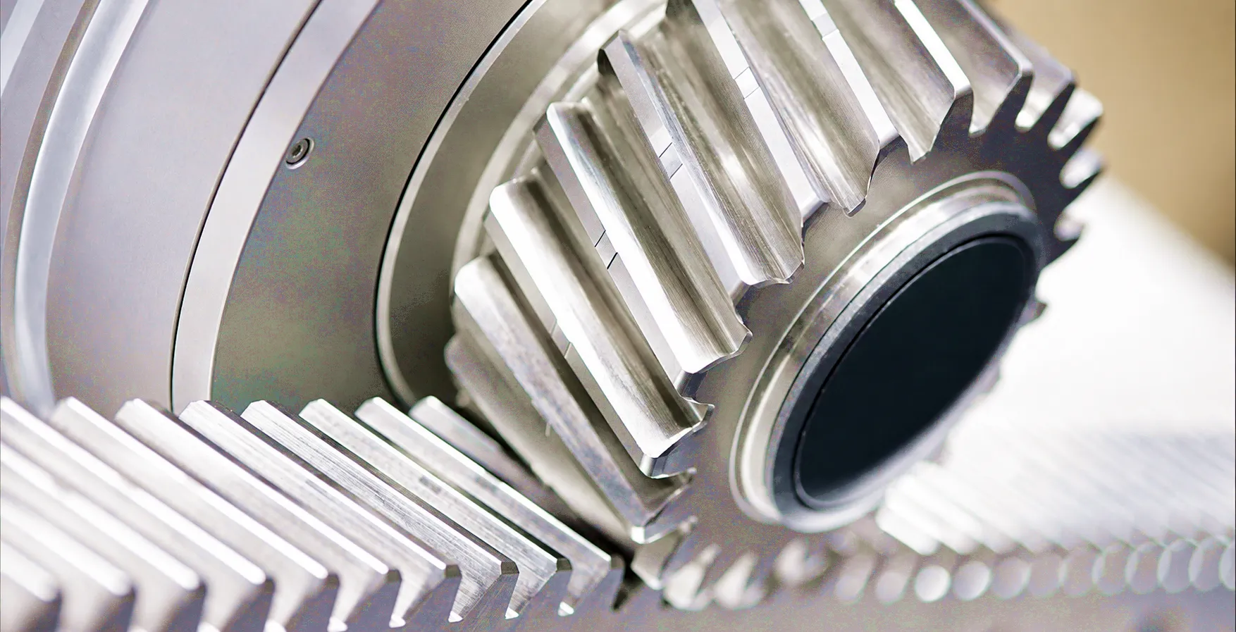
The practical limitation of hobbing for gear racks is surface finish and profile accuracy. A well-executed hobbing pass on a rigid machine with a sharp, correctly relieved hob will produce an Ra surface roughness of 1.6–3.2 µm on the tooth flanks, and pitch errors in the range of ±0.025 mm to ±0.050 mm over a 300 mm span — sufficient for DIN Class 8 or 7 depending on process control. When applications demand higher positional accuracy, lower noise, or the ability to run at high speeds without significant vibration, hobbing alone reaches its ceiling, and the subsequent grinding operation becomes necessary. Nevertheless, for the large segment of UK industrial applications — conveyor systems, agricultural machinery, general automation — hobbed racks at DIN Class 7 or 8 represent the optimal balance of precision and cost.
Peripheral Milling: Versatility for Custom and Prototype Racks
Peripheral milling of gear rack teeth uses either a disc-type involute cutter or an end mill following a programmed CNC path to remove material tooth by tooth. Unlike the continuous generating motion of hobbing, form milling is an indexing process: the cutter machines one tooth space to completion, the workpiece indexes by exactly one pitch, and the process repeats along the full rack length. On a modern 5-axis CNC machining centre — precisely the type of equipment operated in Sheffield’s advanced manufacturing district and Coventry’s precision engineering shops — this approach offers a flexibility that hobbing cannot match. Tooth modules from 0.5 to 20 or beyond can be cut with a small library of indexable cutters and appropriately adjusted CNC programs, making milling the natural choice for prototype gear racks, short production runs, unusual modules, and very large cross-sections that exceed practical hobbing capacity.
The tooth profile accuracy achievable through form milling depends critically on the quality of the cutter’s involute geometry and the rigidity of the machine-fixture-workpiece system. A sharp, properly-ground disc cutter mounted on a rigid arbour in a well-tuned CNC machining centre can achieve DIN Class 9 to Class 8 accuracy on C45 steel racks at modules up to 6 or 8. For higher-quality results, finishing passes with reduced depth of cut and chip load are applied, and the effective accuracy creeps toward Class 7 before the process becomes difficult to justify economically compared to adding a grinding step. One meaningful advantage of the milling route is its ability to machine gear rack teeth directly onto complex part geometries — integrated racks machined into slide plates, curved guide housings, or large weldments — where the workpiece cannot feasibly be set up on a dedicated gear hobbing machine. The UK’s hydraulic engineering sector, particularly companies producing custom linear actuator assemblies and specialised fluid power equipment, regularly specifies milled gear racks because the rack is only one feature among many on a complex fabrication.
From a material standpoint, milling handles an even wider range of workpiece materials than hobbing, including hardened steels (up to approximately 45 HRC with carbide cutters), stainless steels, cast iron, and non-ferrous alloys including aluminium gear racks for lightweight motion systems. This breadth of material compatibility reinforces milling’s role as the process of choice when the application’s material specification is unusual or when the order quantity does not justify the tooling investment of setting up a hobbing operation.
Precision Grinding: Achieving DIN Class 5 and Above
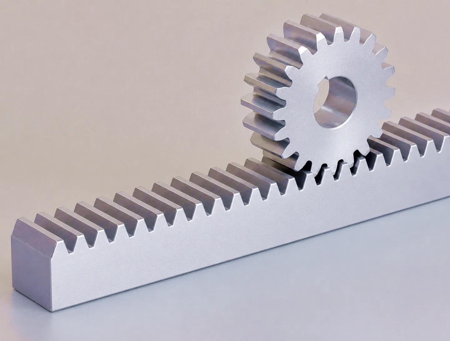
Precision gear rack grinding is where the process chain steps into a different performance class entirely. After a gear rack has been hobbed or milled, heat-treated to the required core hardness and surface hardness specification (commonly 58–62 HRC on the tooth flanks via case hardening or induction hardening of 42CrMo4 or 20CrMnTi steels), and thermally stabilised, it passes to the grinding department where a dressed abrasive grinding wheel removes the remaining stock from the tooth flanks and root in a controlled generating or profile-form grinding operation. The material removal per pass is typically 0.005–0.020 mm — just enough to correct heat-treatment distortion and establish the final surface finish — which preserves the subsurface compressive residual stress layer that is so valuable for fatigue resistance.
Profile grinding uses a wheel dressed to the full tooth space geometry, removing material from both flanks and the root simultaneously in a plunge-and-traverse motion. Generating grinding, the higher-accuracy alternative, uses a disc or worm-type grinding wheel that generates the involute through a rolling motion analogous to hobbing — and for gear racks this generating grinding approach is the route to DIN ISO Class 5 or Class 4 accuracy, with individual pitch errors below ±0.006 mm and cumulative pitch error over a 300 mm span below 0.012 mm. These are the accuracy grades specified for servo-driven CNC machining centres, high-speed linear gantries in electronics manufacturing, and coordinate measuring machine (CMM) drives where sub-micron positional repeatability is the engineering requirement. The tooth flank surface finish achievable after grinding is Ra 0.4–0.8 µm, transforming contact behaviour, noise signature, and lubricant film retention compared to a hobbed rack at Ra 1.6–3.2 µm.
You can see the practical result of this process in products like the Precision Ground Helical Rack, which combines the favourable contact ratio of helical tooth geometry with the surface quality that only grinding can deliver. For applications where noise, vibration, and harshness (NVH) budgets are tight — medical imaging equipment moving gantries, for instance, or semiconductor handling robots — the grinding-derived surface finish is not an optional upgrade but a functional requirement. The investment in grinding reflects directly in working life, with well-ground hardened racks in lubricated enclosed drives routinely achieving 30,000 hours or more before refurbishment is required in well-maintained UK plant environments.
Core Materials in Gear Rack Manufacturing
The workhorse material for standard hobbed and milled racks. Good machinability, moderate strength (tensile strength 700–850 MPa after normalising), and wide availability from UK steel stockholders including Midland Steel and metals distributors across the Black Country corridor. Suitable for DIN Class 7–9 applications without post-grind operations, and readily flame or induction hardened to 50–55 HRC surface hardness for improved wear resistance at moderate cost.
The preferred material for precision-ground gear racks in high-load servo applications. Chromium-molybdenum alloying delivers excellent hardenability through-section, a core tensile strength of 1,000–1,200 MPa after quench and temper, and predictable distortion behaviour during induction hardening — all critical for maintaining DIN Class 5/6 accuracy through the grinding step. The majority of precision rack stock used in UK machine tool and aerospace jig manufacturing is specified as 42CrMo4 or the equivalent EN 1.7225.
Used where corrosion resistance outweighs maximum load capacity — food processing lines in Yorkshire and Lancashire, pharmaceutical cleanroom conveyor drives, and marine applications along the UK coast. Machinability is lower than carbon steel, requiring slower cutting speeds and sharper cutting edges, but the combination of acceptable strength and excellent corrosion resistance makes stainless racks an attractive alternative to carbon steel racks requiring costly protective coatings in aggressive environments.
Injection-moulded or machined polymer gear racks occupy a distinct niche in low-load, noise-sensitive, or dry-running applications. Nylon PA66 and acetal (POM) offer self-lubricating properties, low inertia, electrical non-conductivity, and excellent chemical resistance. Common applications include office automation, medical equipment drawer drives, and light-duty consumer product mechanisms where the noise of a metal rack would be unacceptable and the structural loads remain well within polymer limits.
Technical Advantages of Precision-Manufactured Gear Racks
Unlike ball screws or linear actuators, gear racks can be produced and joined end-to-end to create travel paths of any practical length. Precision-matched jointing kits allow continuous rack runs of 10 m, 20 m, or beyond with maintained pitch accuracy at every join, which is a decisive advantage in long-travel gantry robots and automated storage and retrieval systems (AS/RS) operating in UK logistics warehouses.
A hardened steel gear rack can transmit tangential forces in excess of 50 kN per mesh on large-module (module 8–12) heavy industrial configurations — a force level completely beyond the capability of timing belts or friction drive systems. This makes gear rack drives essential in applications such as steel mill roll-changing carriages, offshore platform handling equipment, and heavy portal milling machines where the moved mass and cutting forces both demand high force capacity.
The positive tooth engagement of a gear rack and pinion provides extremely high positional stiffness — the resistance to being displaced from commanded position under external load. Unlike friction-based drives, a rack system does not creep under sustained force, making it the preferred drive mechanism for press brakes, injection moulding platens, and vertical axis machine tools where gravity loads would otherwise cause unacceptable position drift.
A well-lubricated and correctly preloaded gear rack drive wears progressively and predictably, unlike ball screws that can fail suddenly as a result of ball recirculation fatigue. UK maintenance engineers appreciate that individual rack sections can be replaced without disturbing the rest of a long drive axis, that pinion replacement can restore most of the system’s original backlash characteristics, and that standard metric modules allow interchangeability across multiple suppliers.
Helical gear racks, with helix angles of 14° or 20°, achieve a contact ratio substantially above 1.0 at all operating velocities — meaning that multiple teeth are always sharing the mesh load. This overlapping engagement is what gives helical racks their characteristic smooth running, reduced vibration, and lower noise emission compared to spur racks, particularly at rack velocities above 1 m/s where spur rack engagement impulse becomes audible and mechanically significant. The Induction Hardened Helical Rack with Surface Treatment combines this smooth engagement geometry with surface hardness levels that deliver long service life in demanding continuous-duty drive systems.
Gear Rack Technical & Performance Parameter Reference Table
| Parameter | Hobbed Rack (C45) | Induction Hardened Rack (42CrMo4) | Precision Ground Rack (42CrMo4) |
|---|---|---|---|
| Module Range | 1 – 8 | 1 – 12 | 1 – 8 |
| DIN Accuracy Class | Class 8 – 7 | Class 8 – 6 | Class 6 – 4 |
| Tooth Flank Surface Finish (Ra) | 1.6 – 3.2 µm | 1.6 – 3.2 µm | 0.4 – 0.8 µm |
| Surface Hardness (Tooth Flank) | 170 – 220 HB (as machined) | 55 – 62 HRC | 58 – 62 HRC |
| Core Tensile Strength | 700 – 850 MPa | 1,000 – 1,200 MPa | 1,000 – 1,200 MPa |
| Pitch Cumulative Error (300 mm) | ± 0.040 – 0.060 mm | ± 0.020 – 0.040 mm | ± 0.006 – 0.012 mm |
| Typical Max Tangential Force (M4) | 3,500 N | 7,200 N | 9,500 N |
| Available Lengths (standard) | 500, 1000, 1500, 2000 mm | 500, 1000, 2000 mm | 500, 1000, 2000 mm |
| Tooth Profile Standard | DIN 867 (20° PA) | DIN 867 / ISO 53 | DIN 867 / ISO 1328 |
| Gear Type Options | Spur (straight) | Spur / Helical 14°, 20° | Spur / Helical 14°, 20° |
Industrial Application Scenarios Across UK Manufacturing
Customer Success Story: Sheffield Aerospace Tooling Manufacturer
A Sheffield-based manufacturer producing large composite layup jigs and assembly fixtures for the UK’s aerospace supply chain was experiencing repeatable positioning errors in a five-metre long horizontal axis that drove a heavy gantry overhead carriage. The axis had been running on a hobbed C45 spur rack at DIN Class 7 — an adequate specification for the original design intent — but a series of programme changes to the customer’s composite cure tooling had required higher positional accuracy than the existing system could deliver. The cumulative pitch error of 0.052 mm over the 5 m run was creating measurable geometric distortion in the finished composite panels.
Ever Power’s engineering team was engaged through the company’s UK technical contact. After reviewing the CMM traces supplied by the customer and the drive system specifications — a 1.5 kW servo motor with a 5:1 planetary gearhead driving a module 4 pinion at up to 0.8 m/s — Ever Power proposed a complete rack replacement with precision-ground helical 42CrMo4 racks at DIN Class 5, module 4, helix angle 20°, 2,000 mm lengths with matched pitch joints. Material test certificates to EN 10204 3.1 and full dimensional inspection reports per DIN ISO 1328 were supplied with each rack section, satisfying the customer’s AS9100-aligned quality documentation requirements.
Following installation and recommissioning — with the original servo drive parameters unchanged — the customer recorded a cumulative pitch error of 0.009 mm over the full 5 m run and individual pitch errors below ±0.004 mm at every tooth. The composite panel geometric accuracy improved immediately, eliminating the rework cost that had been running at approximately £8,000 per month. The system has been in continuous three-shift operation for 14 months without any measurable increase in backlash, and the customer has since specified Ever Power ground helical racks for two additional axes on a new rotary assembly jig installation in their Rotherham satellite facility.
What Our Customers Say
“The DIN Class 5 ground helical racks from Ever Power transformed our gantry axis performance. The dimensional documentation package met our AS9100 requirements without any back-and-forth, which saved our procurement team significant time. Lead time was exactly as quoted — 12 working days to our Sheffield receiving dock.”
“We’ve been sourcing induction-hardened module 6 spur racks from Ever Power for our AS/RS stacker crane refurbishment programme. The consistency between batches is genuinely excellent — our CMM checks on the last three deliveries showed less than 0.003 mm variation in tooth pitch across the full 2,000 mm sections. Competitive pricing and straightforward DDP shipping to our Northampton warehouse.”
“We needed 316 stainless steel module 2 racks for a food-grade conveyor redesign at our Yorkshire production site. Ever Power handled the electropolishing specification alongside the machining — the hygiene surface finish requirements were met first time, and the material certificates were fully traceable to the billet heat number. Their customisation capability on small quantities genuinely sets them apart from standard catalogue suppliers.”