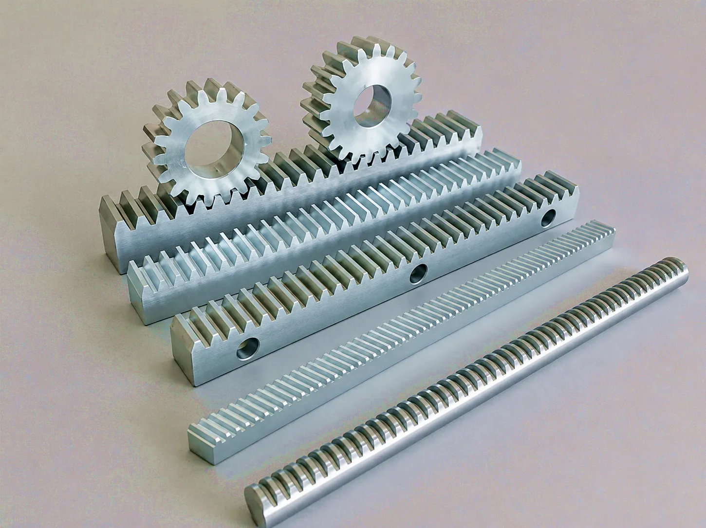
How a Rack and Pinion Drive Actually Works
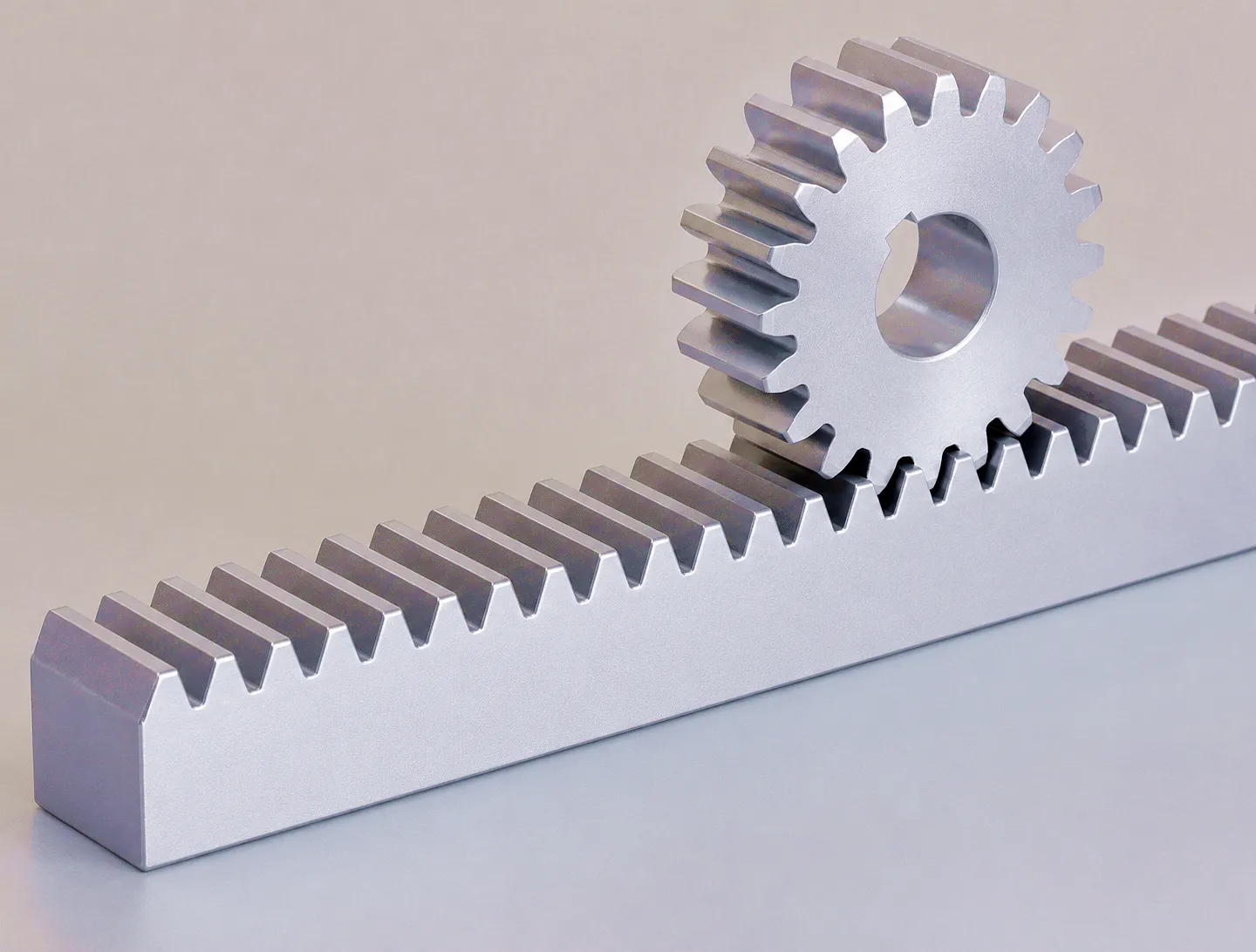 The gear rack is a linear gear — a gear with an infinite pitch circle radius, so its teeth are arranged in a straight line rather than around a disc. When a circular pinion gear meshes with this rack, the rotational motion of the pinion causes the rack to translate in a straight line. The linear speed of the rack is equal to the angular velocity of the pinion multiplied by the pitch circle radius of the pinion. This relationship is expressed as: v = ω × r, where v is linear velocity in metres per second, ω is angular velocity in radians per second, and r is the pitch radius of the pinion. More practically, if the pinion has a pitch diameter of 40 mm and rotates at 1,500 rpm, the rack will travel at approximately 3,142 mm per second — or just over 3 metres per second. In applications across UK aerospace tooling facilities and heavy fabrication shops in the West Midlands, this velocity figure is a primary design input that determines servo sizing, stroke length, and cycle time.
Force transmission follows a complementary relationship. The tangential force delivered at the rack tooth face equals the driving torque divided by the pinion pitch radius: F = T / r. This means that for a given motor torque, using a smaller pinion increases the force delivered to the rack — at the cost of proportionally lower linear speed. Drive engineers refer to this as the mechanical advantage of the rack and pinion, and it is exploited deliberately in applications ranging from gantry robots in automotive body shops to CNC router beds in aerospace composite manufacturing. However, theoretical force must always be discounted by efficiency losses: friction in the tooth mesh, bearing drag, lubrication viscosity, and rack straightness all reduce the force that actually reaches the carriage or workpiece.
Speed scales linearly with pinion radius and rotational rate.
Smaller pinion radius multiplies force; larger radius increases speed.
Core Materials — What the Rack Is Made From Matters More Than You Think
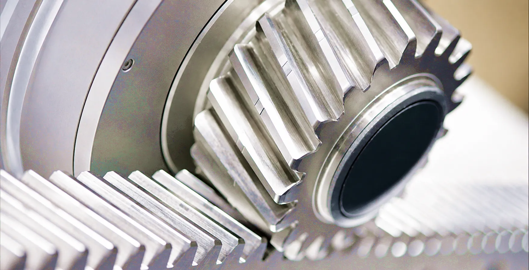 Material selection is probably the most consequential early-stage decision in gear rack design, and it directly governs what speed and force envelope is achievable in service. The most widely used material in industrial gear rack manufacture is carbon steel in grades such as C45 (equivalent to 080M46 in the UK BS standard), chosen for its excellent machinability, reasonable cost, and the ability to develop a hard tooth surface through induction hardening or case-hardening treatments. When properly hardened, C45 steel rack teeth can achieve surface hardness values of HRC 45–55, giving tooth surfaces that resist pitting, abrasion, and plastic deformation even under dynamic loading. For UK precision engineering firms — particularly those based in Leicester’s tooling sector or Coventry’s automotive supply chain — these material properties translate directly into predictable service life and lower whole-life cost.
Best for: General industrial, CNC
Standard in UK market
Best for: Heavy cranes, gantries
Superior fatigue life
Best for: Food, pharma, labs
Lower load rating
Best for: Medical, lab automation
Low load, high precision
Product Advantages — Why Rack and Pinion Outperforms Rival Linear Drive Technologies
In any design review where ball screws, linear motors, or chain drives are on the table alongside gear rack and pinion, the rack solution carries a compelling set of structural advantages. The most important is unlimited stroke length. Ball screw drives are practically limited to travel lengths of around 4–6 metres before column buckling and critical speed become unmanageable engineering problems. Gear rack drives have no such constraint — rack segments can be precision-joined end-to-end to create travel lengths of 10, 20, or even 100 metres, which is why gear rack dominates in long-travel CNC machining centres, gantry cranes used in UK shipbuilding yards at Barrow-in-Furness, and automated warehouse aisle systems. For the growing UK logistics automation sector — driven by major distribution centre expansions across the Midlands and the North — this scalability has made rack and pinion the default choice in most ASRS (Automated Storage and Retrieval System) designs.
Gear Rack Technical and Performance Specification Table
The following specification table covers the most critical parameters that determine how a gear rack performs in real drive applications. These figures reflect the ranges available across Ever Power’s standard and custom product lines, and they span the typical requirements of UK industrial procurement from light automation through to heavy-duty gantry and crane systems. Procurement engineers and OEM designers should use these as a baseline for system design and early-stage supplier discussions. Custom modules, lengths, tooth profiles, and surface treatments are available outside these ranges on request.
| Parameter | Standard Range | High-Precision Grade | Unit / Note |
|---|---|---|---|
| Module (m) | 1 – 10 | 1.5 / 2 / 3 / 4 (precision ground) | mm / tooth |
| Tooth Profile | Straight (Spur) | Helical (20° helix typical) | 20° pressure angle standard |
| Accuracy Grade | DIN 10 – DIN 8 | DIN 7 – DIN 5 | Per DIN 3962 / ISO 1328 |
| Pitch Accuracy | ±0.05 mm / 300 mm | ±0.01 mm / 300 mm | Ground tooth flank |
| Material | C45 Steel | 42CrMo4 / 316 SS / PA66 | Custom alloys on request |
| Surface Hardness | HRC 45 – 50 (induction) | HRC 54 – 60 (case carburized) | Core: 28–35 HRC |
| Section (W × H) | 15×15 to 60×60 mm | Custom cross-sections | Standard lengths to 2000 mm |
| Max Tangential Force (Ft) | Up to 25 kN (m4, C45) | Up to 80+ kN (m8, 42CrMo4) | Depends on module + material |
| Operating Speed | Up to 3 m/s | Up to 10 m/s (helical, ground) | Application dependent |
| Surface Treatment | Phosphate / Black oxide | Nickel plate / Zinc / Hard chrome | Corrosion and wear control |
| Backlash | 0.04 – 0.10 mm | < 0.010 mm (zero-backlash system) | With anti-backlash pinion unit |
Industrial Application Scenarios — Where Rack and Pinion Drive Systems Deliver
CNC Machining Centre Axis Drives — Sheffield and West Midlands Tool Shops
In high-throughput CNC machining centres, the gear rack and pinion drive provides the X and Y axis motion that determines both how fast a part is machined and how accurate the finished dimensions are. Sheffield’s long-established precision engineering community — still home to firms supplying the aerospace and defence sectors — relies on ground helical rack systems with DIN 5 or better accuracy to hold tolerances of ±0.01 mm across full-bed travel. The helical tooth form distributes contact stress across multiple teeth simultaneously, reducing noise and vibration at speeds that can reach 60 m/min rapid traverse. For a machine tool builder designing a five-axis centre with 4-metre X-axis travel, the rack and pinion approach is essentially mandatory — no other drive technology delivers the same combination of stiffness, speed, and travel length at a comparable capital cost. Related products such as the V-type ground straight guide rack are widely specified in conjunction with linear guide rail systems to provide combined guidance and drive from a single machined datum surface.
Automotive Body Shop Gantry Robots — Birmingham and Coventry Production Lines
The automotive body shops concentrated around Birmingham and Coventry — including facilities feeding Jaguar Land Rover’s manufacturing operations — deploy gear rack and pinion drives as the backbone of their overhead gantry robot systems. These gantries traverse welding, sealing, and assembly robots over distances of 20–50 metres, with cycle times measured in seconds and positional accuracy requirements in fractions of a millimetre. The gear rack drive here is chosen for its ability to deliver consistent positioning across extreme travel lengths and to withstand the vibration, thermal cycling, and weld spatter contamination that are inherent to this environment. Induction-hardened helical rack with phosphate surface treatment is the standard specification, providing a tooth surface hardness that resists the abrasive wear caused by metal particulate contamination, while the helical profile keeps running noise below 72 dB(A) even at gantry traverse speeds of 120 m/min.
Bridge Cranes and Port Handling Equipment — Teesside and Barrow-in-Furness
Heavy industrial lifting environments demand a gear rack drive system that can withstand years of continuous service under loads that dwarf anything seen in a machine tool. Bridge cranes at the steel processing and port handling facilities in Teesside, and submarine assembly buildings at Barrow-in-Furness, use large-module gear rack systems — typically m8 to m12 — in alloy steel, often with full-section through-hardening rather than surface treatment alone. These applications define the extreme end of the force output envelope for rack and pinion: tangential forces exceeding 100 kN are common, and dynamic shock loads during hoisting can be two to three times the static rating. Drive system design in these environments always includes a substantial safety factor and typically involves a detailed FEA review of the rack mounting arrangement to ensure that bending and deflection under load remain within the rack’s permissible range. Lubrication strategy — usually automated grease application via pinion-mounted dispensers — is a critical maintenance engineering consideration.
Automated Warehouse and ASRS Systems — Midlands Logistics Hubs
The expansion of automated warehousing across the Midlands and Thames Valley has driven massive growth in demand for gear rack drives suited to storage and retrieval machines. Shuttle vehicles and stacker cranes in these systems travel aisles of 30–100 metres at speeds of 4–6 m/s with positioning accuracy requirements of ±2 mm, repeated tens of thousands of times per shift across the system’s 20-year design life. The drive specification in ASRS environments prioritises consistent rack quality across long joined sections — cumulative pitch error must stay within tight limits over the entire aisle length to prevent positioning drift — and the rack mounting structure must accommodate thermal expansion without losing mesh geometry. The rectangular guide rail systems used alongside rack drives in these applications provide the structural reference that keeps the pinion in correct mesh throughout. Lubrication management is simplified by the use of permanently lubricated pinion units and periodic grease replenishment.
Pharmaceutical and Food Processing Lines — Yorkshire and East Midlands Facilities
In regulated production environments — pharmaceutical tablet lines in Nottingham and food processing facilities in Yorkshire — the gear rack drive must meet an entirely different set of requirements. Corrosion resistance, cleanability, freedom from lubrication contamination risk, and compliance with FDA and BRC audit requirements take priority over raw force or speed capability. Stainless steel racks in 316 grade, combined with food-grade NLGI 2 grease or dry-film lubricants, are the standard specification in these environments. Positioning accuracy requirements are typically modest compared to machine tool applications — filling and capping machines rarely need better than ±0.5 mm — but reliability and uptime are paramount: an unplanned stoppage on a high-speed packaging line costs thousands of pounds per hour in lost output. The use of engineering plastic or anodised aluminium rack in very light-duty conveying and labelling equipment eliminates lubrication entirely, which is increasingly preferred in clean-room pharmaceutical environments.
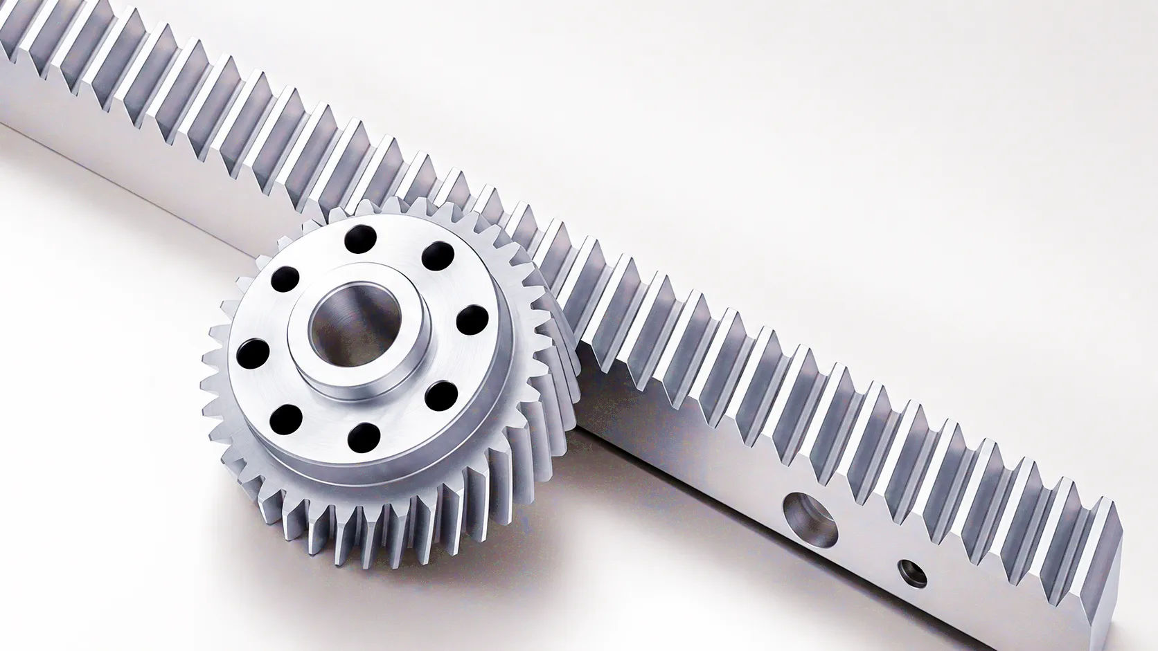 Ever Power’s gear rack manufacturing facility is built around a production philosophy that treats precision, repeatability, and customer-specific engineering as non-negotiable standards — not premium add-ons. Our CNC gear grinding lines produce rack tooth flanks to DIN 5 accuracy as a standard output, with in-process CMM verification at every production stage. This level of process control is what allows UK customers — from specialist machine tool builders in Huddersfield to defence primes managing long-lead procurement — to specify Ever Power gear rack with confidence that the delivered product will meet its rated specification without incoming inspection surprises or post-installation shimming.
Customer Success Story — Sheffield Aerospace Component Manufacturer
Case Study | Sheffield, South Yorkshire
 A medium-sized aerospace component manufacturer based in Sheffield — supplying structural titanium machined parts to a Tier 1 prime contractor — was facing a chronic throughput problem on their flagship five-axis CNC machining centre. The machine’s X-axis drive, using an ageing ball screw assembly, was limiting traverse speed to 22 m/min and required bi-annual replacement of the screw due to ball recirculator wear under the high loading imposed by their titanium workpieces. The combination of downtime for screw replacement, the screw itself, and the associated re-commissioning costs was running at approximately £38,000 per year — a figure their operations director described as “a slow but persistent drain on margin.”
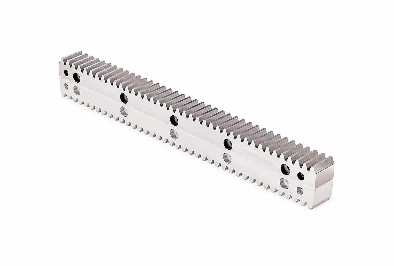
The company approached Ever Power following a recommendation from a sister plant in the West Midlands that had already converted a plasma cutting gantry to rack and pinion drive. Ever Power’s UK technical sales team reviewed the machine’s axis load data and traverse profile and proposed a retrofit package: precision ground helical rack in 42CrMo4, module 4, DIN 6 accuracy, paired with a zero-backlash pinion unit incorporating an integrated spring-preload mechanism to eliminate reversal backlash without the need for rack-side adjustment. The rack was cut to 3-metre sections and supplied with pre-drilled and counterbored mounting holes referenced to the machine’s existing T-slot pattern, significantly reducing the installation time.
Following installation and servo re-parameterisation, the X-axis traverse speed increased to 48 m/min — a 118% improvement — while positioning repeatability measured at ±0.009 mm over full stroke, comfortably inside the ±0.015 mm tolerance the aerospace application demanded. Eighteen months after the retrofit, the rack and pinion drive showed no measurable wear in routine inspection, and the operations director confirmed that the annual maintenance cost for the X-axis had fallen to under £2,000 — a reduction of more than 94% compared to the ball screw arrangement it replaced. The payback period on the retrofit investment was calculated at 11 months.
What UK Customers Say About Ever Power Gear Rack
“The pitch accuracy on the ground helical rack was measurably better than the spec sheet — we verified it on our CMM before installation and got ±0.008 mm per 300 mm. For a CNC axis retrofit that’s exceptional. Ever Power’s UK technical team was responsive and clearly understood what we needed without us having to over-specify.”
“We specified a non-standard rack cross-section for our gantry robot — 32 mm wide by 22 mm high, which none of our existing suppliers could produce economically. Ever Power turned around a custom quotation in 48 hours and had the first samples with us in 19 working days. The induction hardness profile was verified by our materials lab and met spec exactly. This is now our preferred source for all rack requirements.”
“The 316 stainless rack we ordered for our washdown conveyor system has been running for 14 months in a high-pressure steam cleaning environment without any visible corrosion or tooth wear beyond what our predictive maintenance model forecast. The DDP delivery to our Yorkshire site was straightforward and the customs documentation was complete. Would recommend without reservation for food-sector applications.”
Frequently Asked Questions — Gear Rack and Pinion Drive Systems
Ready to specify the right gear rack for your UK application?
Ever Power’s engineering team responds to all technical and commercial enquiries within one UK business day.
Get Your Custom Gear Rack Quote →
edit by gzl