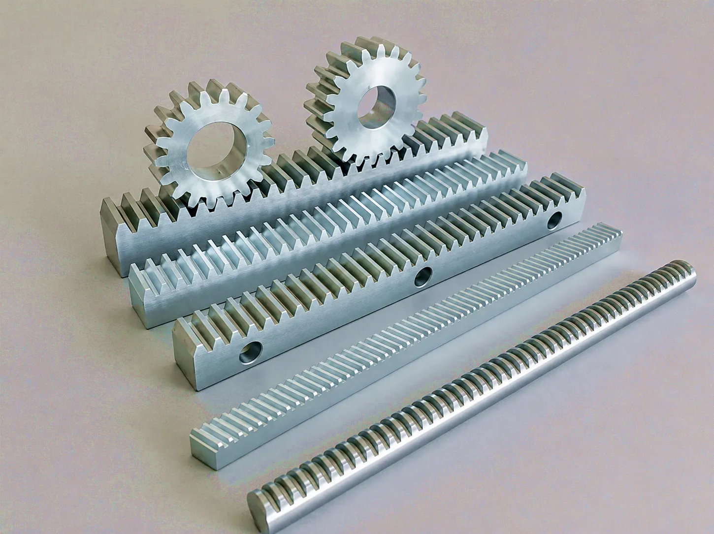
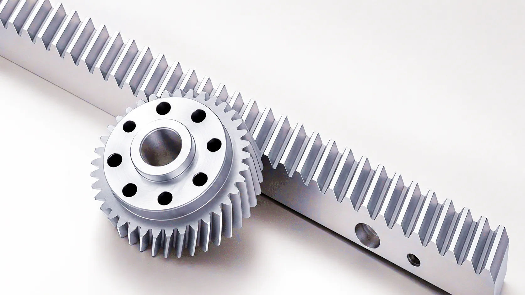
 A gear rack is a toothed bar or strip — flat or round in cross-section — that converts rotational motion from a mating pinion gear into precise linear displacement. Unlike other power transmission components that keep energy circulating within rotating shafts, a gear rack anchors one half of the mechanism and turns every degree of pinion rotation into a measurable increment of straight-line travel. This deceptively simple principle underpins some of the most demanding equipment in British manufacturing, from the precision CNC machining centres that line the factory floors of Birmingham’s metalworking corridor to the heavy gantry cranes serving Sheffield’s steel processing facilities. Understanding what a gear rack actually is — its geometry, its material science, its range of tooth profiles and surface treatments — is the starting point for any engineer selecting linear drive solutions. The rack-and-pinion system has been used in mechanical engineering for centuries, yet modern manufacturing techniques have pushed its accuracy, load capacity and service life to levels that would have been unthinkable even two decades ago. Whether you are specifying a replacement component for an ageing conveyor or designing a high-speed automation line from scratch, the fundamentals of gear rack selection remain consistent: module, material, accuracy grade, and lubrication regime all interact to define the system’s real-world performance ceiling. This article examines each of those variables in depth.
How Does a Gear Rack Work? The Mechanics Explained
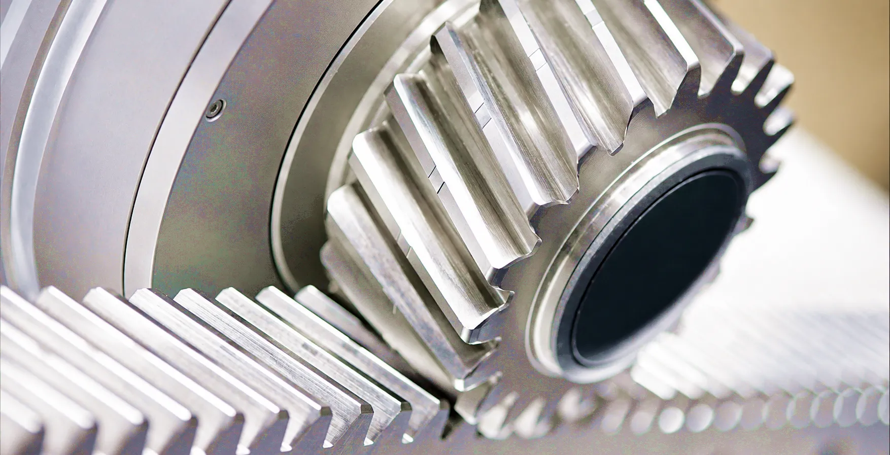
The operating principle of a gear rack centres on the meshing interface between two conjugate tooth profiles. A circular pinion gear — mounted on a motor or gearbox output shaft — rotates against the linear rack, whose teeth are cut at a consistent pitch along its length. As the pinion turns, each successive tooth engages the next rack tooth, pushing the rack (or the carriage riding on the rack) along a straight path. The relationship between angular pinion rotation and linear displacement is entirely predictable: linear travel equals the pinion’s pitch circle circumference multiplied by the number of revolutions, expressed simply as distance = pi × d × n, where d is the pitch diameter and n is the number of revolutions. This mathematical precision is what makes rack-and-pinion drives so attractive for CNC positioning, where repeatable accuracy at micron-level tolerances is required across thousands of operating cycles.
Tooth profile geometry defines much of the system’s character. The involute profile — the standard in virtually all modern gear racks — ensures that the contact force between pinion and rack always acts along a constant pressure angle, typically 20 degrees for most industrial applications. This geometry maintains smooth, low-noise transmission even as manufacturing tolerances produce slight variations in centre distance. Helical gear racks, where teeth are cut at an angle to the rack’s longitudinal axis, introduce a component of oblique tooth engagement that further reduces instantaneous load concentration, lowers noise, and allows higher continuous force ratings. Straight (spur) racks offer simpler installation geometry and remain the preferred choice where axial loading on the pinion bearings must be minimised. The choice between spur and helical, between metric module and diametral pitch, and between left-hand and right-hand helix angles all cascade into downstream decisions about pinion selection, mounting hardware and lubrication strategy.
Key Principle
Linear displacement = π × Pitch Diameter × Revolutions. Every full pinion revolution advances the rack by exactly one pitch circle circumference — a relationship that never drifts, never slips, and scales predictably from sub-millimetre increments to multi-metre traverses.
Core Materials Used in Gear Rack Manufacturing
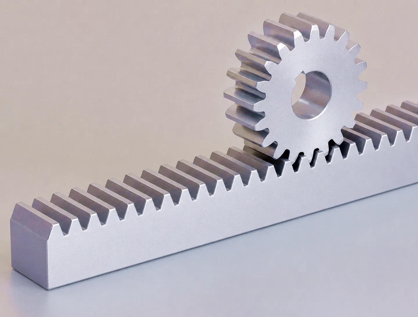 Material selection for a gear rack is not a minor detail — it defines the component’s load ceiling, its fatigue life, its suitability for food-grade or corrosive environments, and the post-machining heat treatment options available to the manufacturer. Medium carbon steel grades such as C45 and S45C are the industry workhorses. They machine readily, accept induction hardening to surface hardness levels of 55–60 HRC while maintaining a tough, ductile core, and offer a balance of strength and cost that suits the majority of industrial drive applications. Rack teeth hardened by induction present a wear-resistant contact surface, while the unhardened rack body absorbs impact without catastrophic fracture — a combination that suits the punishing duty cycles typical of automated production lines in the East Midlands automotive supply chain.
Where higher strength-to-weight ratios are demanded, alloy steel grades 42CrMo4 (EN 19 in British Standard nomenclature) and 20CrMnTi enter the specification. These materials achieve significantly higher core tensile strength after heat treatment and are preferred in aerospace ground support equipment, heavy machine tools, and applications where the rack cross-section must be kept slim to clear adjacent components. Stainless steel racks — most commonly 304 and 316 grades — sacrifice some load capacity but are indispensable in food processing plants, pharmaceutical manufacturing facilities, and marine environments where corrosion resistance and washdown compatibility outweigh raw mechanical performance. Polymer and nylon racks occupy a different niche entirely: silent, self-lubricating, and chemically inert, they serve light-duty automation, medical devices and electronics manufacturing where metal contamination risks are unacceptable.
C45 / S45C Steel
Standard industrial workhorse. Induction hardenable to 55–60 HRC. Excellent machinability. Cost-effective for high-volume applications.
42CrMo4 Alloy Steel
High-tensile alloy. Used in aerospace ground support and precision machine tools. BS EN 19 equivalent. Superior core strength after heat treatment.
Stainless 316L
Fully corrosion-resistant. Food-grade and pharmaceutical applications. Marine-grade protection. Ideal for washdown environments.
PA66 / POM Nylon
Self-lubricating, low noise, chemical resistance. Light-duty automation, medical devices and electronics sectors. Zero metal contamination risk.
Key Technical Advantages of Gear Rack Drives
Rack-and-pinion drives occupy a distinct performance envelope compared to alternative linear actuation technologies — ball screws, belt drives, hydraulic cylinders and linear motors all have their domains, but a gear rack offers a specific combination of attributes that makes it irreplaceable in many UK industrial settings. The following advantages define why plant engineers in Manchester’s advanced manufacturing sector, robotics integrators in Cambridge’s technology corridor, and machine tool builders throughout the West Midlands continue to specify gear rack drives as their default linear motion solution.
⚡ Unlimited Travel Length
Unlike ball screws, which become impractically flexible beyond about three metres due to column buckling and critical speed limitations, gear racks can be butt-joined end-to-end to achieve traverse lengths of tens of metres. Precision-matched rack segments allow continuous long-axis positioning without accuracy degradation at the joints, making rack drives the standard choice for large gantry systems, bridge cranes and portal milling machines.
🎯 High Force Capacity
The tooth geometry of a hardened steel gear rack transmits very high tangential forces with low contact stress per unit face width. Module 10 helical racks, for example, routinely handle peak thrust loads exceeding 50 kN in heavy machine tool applications, vastly exceeding the capacity achievable with similarly sized belt or chain drives. This force density is particularly valued in Sheffield’s steel processing equipment, where heavy workpiece loads demand reliable, stiff linear actuation.
📈 Precision Repeatability
Ground gear racks achieve pitch accuracy to DIN 5 or better, with total cumulative pitch error over 300 mm typically below 8 micrometres on premium grades. Paired with a precision backlash-eliminating pinion or a zero-backlash rack specification, these systems deliver bidirectional repeatability that satisfies the most demanding CNC machining and semiconductor handling requirements — performance that cannot be matched by pneumatic or hydraulic cylinders without closed-loop feedback.
🔒 Positive Drive — No Slip
The positive mechanical engagement between rack teeth and pinion teeth eliminates the possibility of slip — a fundamental weakness of friction-based drive systems operating under variable load. This characteristic is critical in safety-relevant applications such as rack-and-pinion lifts, elevator systems subject to UK Lift Regulations, and precision cutting machines where unexpected slippage would result in workpiece loss or personnel hazard. The mechanical lock also holds position indefinitely under static load with no energy input.
⚙ Long Service Life
Case-hardened gear rack teeth exhibit excellent fatigue resistance under cyclic bending loads. With proper lubrication — an automatic lubricator feeding SAE 90 gear oil at intervals matched to the traverse duty cycle — ground racks in typical industrial use regularly achieve service lives exceeding 20,000 operating hours. Compared to toothed belt drives requiring replacement every 10,000–15,000 hours under heavy loading, the gear rack offers substantially lower lifecycle cost when amortised over a machine’s service period.
🛠 Wide Customisation Range
Gear racks are available in modules from 0.5 to 32, in spur and helical configurations, with helix angles from 5° to 30°, in lengths from 250 mm to 3,000 mm per segment, and with mounting hole patterns configured to customer drawings. Surface treatments spanning black oxide, zinc plating, nickel plating and hard chrome extend corrosion protection to match the harshness of the installation environment — from clean-room semiconductor fabs to outdoor rail switching systems exposed to British weather year-round.
Technical Specifications and Performance Parameters
The table below summarises the key parameters across our standard gear rack range. Custom specifications — including non-standard modules, extended face widths, special alloy grades and proprietary mounting patterns — are available on request. All dimensional data refers to the metric system in accordance with ISO 54 and DIN 780 standards.
| Parameter | Spur Rack | Helical Rack | Ground Helical Rack | Zero-Backlash Rack |
|---|---|---|---|---|
| Module Range | M1 – M16 | M1 – M16 | M1 – M10 | M1 – M6 |
| Pressure Angle | 20° | 20° | 20° | 20° |
| Helix Angle | 0° (straight) | 15° / 19.5° | 15° / 19.5° | 19.5° |
| Material | C45 / S45C / SS | C45 / 42CrMo4 | 42CrMo4 / SCM440 | 42CrMo4 |
| Surface Hardness | 50–55 HRC (IH) | 54–60 HRC (IH) | 58–62 HRC (IH) | 58–62 HRC (IH) |
| Accuracy Grade (DIN 3962) | Q7 – Q10 | Q7 – Q9 | Q4 – Q6 | Q4 – Q5 |
| Max Segment Length | 3,000 mm | 3,000 mm | 2,000 mm | 1,000 mm |
| Surface Treatment | Black oxide / Zinc | Black oxide / Nickel | Phosphate / Chrome | Phosphate / Chrome |
| Peak Load Capacity | Up to 20 kN (M6) | Up to 35 kN (M8) | Up to 50 kN (M10) | Up to 18 kN (M5) |
Industrial Application Scenarios Across the UK
🏭 CNC Machine Tools — Birmingham & West Midlands
Birmingham’s precision engineering cluster — stretching from the Jewellery Quarter through Solihull and into Coventry’s aerospace supply chain — relies heavily on gear racks as the primary linear drive in multi-axis machining centres. Gantry-type five-axis mills and large-format horizontal boring machines use helical rack drives on their X and Y axes, where traverse speeds of 60–80 m/min combined with positioning repeatability of ±5 micrometres are standard expectations. The precision ground helical rack in DIN 5 accuracy grade is the default specification for this duty, delivering the combination of high-speed travel and fine positioning resolution that modern tool paths demand. Automatic grease lubrication systems — typically set to dispense 0.5 cc per metre of travel — ensure the rack teeth remain properly protected throughout three-shift production schedules. Rack segments are butt-mounted with precision-located dowel pins to maintain pitch continuity across joints, avoiding the step errors that would otherwise appear in long workpiece surfaces.
🏯 Steel Processing & Heavy Industry — Sheffield
Sheffield’s long-established reputation as England’s steel city extends into the processing equipment that lines its rolling mills and forge shops. Heavy-duty gantry cranes, coil handling systems and slab transfer cars all depend on gear rack drives to position multi-tonne loads with the accuracy and reliability that modern just-in-time production schedules demand. Module 10 to 16 induction-hardened racks, mounted on steel fabricated subframes, carry carriage assemblies weighing several tonnes across spans of 20 metres and beyond. The thick rack bodies — typically 40–60 mm in height — resist the bending loads imposed by offset force application, while a case-hardened tooth surface depth of 3–5 mm maintains wear resistance through years of arduous service. Integration with overhead travelling cranes (OTC) in Sheffield’s surviving special steel plants typically requires racks with custom drilled-and-tapped mounting patterns, flange-mounted pinion gearboxes and dual-rack parallel configurations to balance lateral forces on the runway structure.
🤖 Robotic Automation — Greater Manchester
Manchester’s Advanced Manufacturing Research Centre ecosystem has seeded dozens of robotics integrators and automation systems builders across the Northern Powerhouse corridor. Gear rack seventh-axis systems — linear rails that extend a six-axis robot arm’s working envelope along a ground-mounted or overhead track — have become standard in automotive body shop automation, logistics palletising cells and pharmaceutical dispensing lines. The key specification challenge in these applications is minimising cumulative positioning error over traverses of three to ten metres, which demands ground rack at DIN 5 or better, combined with servo drives running closed-loop feedback from a linear encoder mounted alongside the rack. Zero-backlash rack-and-pinion units, achieved through spring-loaded split pinion designs or twin-pinion preload arrangements, eliminate the reversal error that would otherwise compromise pick-and-place repeatability. Cycle times in these cells often push traverse speeds above 150 m/min, which requires careful dynamic analysis of the rack mounting structure to avoid resonance.
🚦 Rack-and-Pinion Lifts — Nationwide Construction
The UK construction sector — particularly the high-rise residential and commercial projects reshaping London’s skyline and driving regeneration in Leeds, Bristol and Edinburgh — relies on rack-and-pinion construction hoists to transport materials and personnel up tower crane mast structures and building cores. These machines operate under the Lifting Operations and Lifting Equipment Regulations 1998 (LOLER) and must achieve duty cycles of hundreds of lifts per day in exposed outdoor conditions. The gear racks in construction hoists are hot-dip galvanised or geometrically self-draining to resist the accumulation of rainwater, and are subject to periodic inspection under LOLER. Load-rated racks for this application carry CE marking and full material traceability documentation — compliance requirements that responsible UK suppliers treat as a minimum baseline rather than a differentiator.
⛈ Rail Track Geometry & Infrastructure
Beyond conventional factory floors, gear racks appear throughout Britain’s rail infrastructure in applications ranging from rack-assisted mountain railway sections — most famously the Snowdon Mountain Railway, which uses a Abt-system rack between the running rails — to station platform screen door systems and automatic buffer stops in sidings and depots. Rail infrastructure applications demand racks with full dimensional documentation to Network Rail specifications and, where applicable, compliance with TSI (Technical Specification for Interoperability) requirements under retained UK rail law post-Brexit. The combination of outdoor exposure, vibration loading from passing trains, and the safety-critical nature of railway operation means that both material traceability and periodic condition monitoring form part of the maintenance regime for gear racks in this sector.
Ever Power — Precision Gear Rack Manufacturing & Customisation
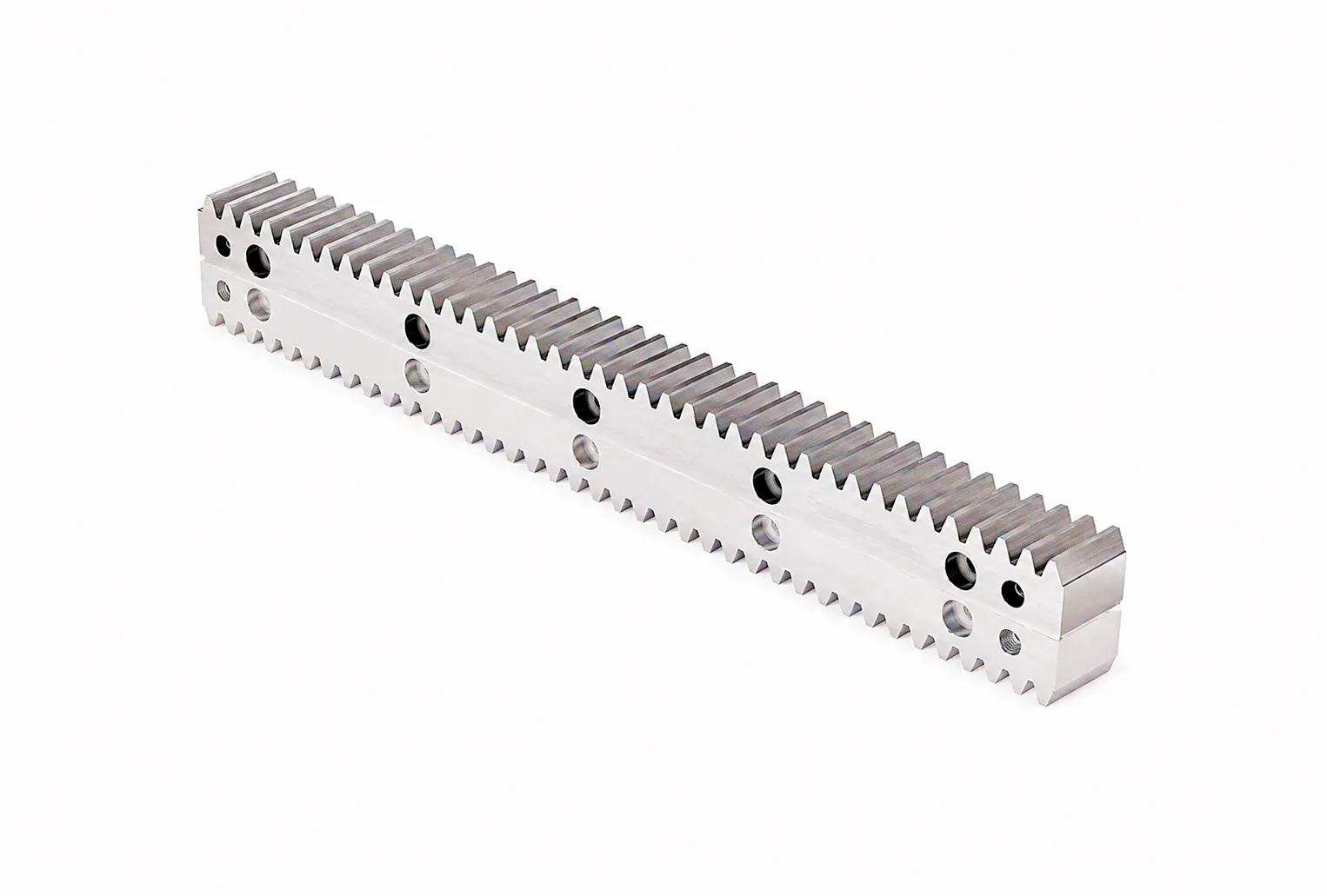 Ever Power has built its reputation over more than two decades on a single, non-negotiable principle: every gear rack that leaves our manufacturing facility must meet or exceed the dimensional and mechanical performance specification agreed with the customer, without exception. That commitment begins at material receipt — where incoming steel is subject to spectrographic composition verification and hardness billet testing — and extends through tooth hobbing, induction hardening, precision grinding, surface treatment and final inspection using Zeiss coordinate measuring machines with sub-micron measurement uncertainty. Our production capacity spans module 0.5 miniature racks for medical robotics through to module 32 heavy-duty racks for crane and mining applications, all manufactured on CNC gear hobbing and grinding equipment with full process traceability documentation provided as standard.
Customisation capability is where Ever Power genuinely differentiates from catalogue distributors. Our engineering team can accept customer CAD drawings in STEP, IGES or DXF format and produce prototype racks within 15 working days, following which volume production can commence with delivery terms tailored to customer kanban schedules or project milestones. Common customisation requests include non-standard module values, asymmetric tooth profiles for specific load direction applications, integral mounting flanges machined into the rack body, customer-specific mounting hole patterns, and split-rack designs for installation in restricted-access locations. Racks requiring compliance documentation for CE marking, LOLER application or specific EU machinery directive categories are handled by our regulatory team with supporting test records and material certificates provided. Our zero backlash rack series is a particular area of expertise, incorporating split-pinion preload design and precision-matched rack-pinion pairs that eliminate reversal error in high-precision automation systems.
Ready to discuss your gear rack requirements?
Our applications engineers are available to review your drawings, recommend specifications and provide a formal quotation — typically within 24 hours.
Customer Success Story: Sheffield Forge & Fabrication Ltd
Industry: Heavy Steel Processing
Location: Sheffield, South Yorkshire
Sheffield Forge & Fabrication Ltd, a long-established steel section processor serving the UK offshore energy and structural engineering sectors, faced a critical operational problem in late 2023. Their ageing transfer car system — used to position steel billet stock between a walking beam furnace and a two-high rolling mill — was experiencing progressive rack tooth wear on the original milled-tooth mild steel rack installed during the facility’s 1998 refurbishment. The worn teeth were producing positioning errors of up to 15 mm at the downstream end of the 18-metre traverse, causing rolled section lengths to fall outside the ±3 mm tolerance window specified by their structural steel frame manufacturing clients. With the facility running three shifts, six days a week, downtime for rack replacement had to be planned within the plant’s annual maintenance window of just four days.
The plant’s engineering manager contacted Ever Power following a recommendation from a fellow engineer at a Sheffield Forgemasters supply chain meeting. After reviewing the original installation drawings and a dimensional survey report, Ever Power’s applications team specified a module 12, 42CrMo4 alloy steel rack with induction-hardened teeth (58–62 HRC surface hardness) and a zinc-phosphate plus oil surface treatment to resist the mill scale and moisture present in the furnace environment. Nine rack segments of 2,000 mm each were manufactured with precision-matched pitch at segment joints, pre-drilled with the existing mounting hole pattern, and shipped to Sheffield with a four-week lead time from order placement.
The installation team completed the rack replacement within 38 hours of the maintenance window — well within the four-day allowance — including alignment shimming, pinion regashing and lubrication system reconfiguration. On restart, the positioning error measured across the full 18-metre traverse was 0.6 mm, comfortably within the application’s tolerance. Eighteen months after installation, the plant’s condition monitoring team reports negligible wear on the rack tooth surfaces, and the tooth flank finish remains consistent with the as-delivered ground surface specification. Sheffield Forge & Fabrication projects the replacement rack will achieve a service life of at least ten years at current production volumes — compared to the original milled rack’s 25-year life on considerably lighter duty.
What Our Customers Say
“The ground helical rack supplied by Ever Power for our gantry milling machine met the DIN 5 accuracy requirement exactly as stated. Pitch error across the 9-metre traverse was well inside our acceptance limit. The documentation package — material certs, hardness test report and inspection record — was complete and professionally presented. Delivery to our West Midlands site was faster than comparable UK-sourced alternatives at a noticeably competitive price.”
— James Hartley, Engineering Director, Midland Precision Tools Ltd, Wolverhampton
“We specified a zero-backlash rack-and-pinion system for a collaborative robot seventh-axis installation at our Manchester facility. Ever Power’s application engineer responded within four hours with a detailed technical proposal covering rack selection, pinion preload calculation and lubrication specification. The zero-backlash performance has been exceptional — 28 months and over 400,000 traversal cycles into service with no measurable increase in reversal error. We will use Ever Power as our preferred supplier for all future rack procurement.”
— Sarah Briggs, Automation Systems Manager, Northern Robotics Integration Ltd, Manchester
“Ever Power handled our request for custom-module stainless steel racks for a food processing conveyor retrofit with exactly the right blend of technical depth and commercial pragmatism. The team understood our BRCGS facility requirements for stainless construction, provided 316L mill certificates without being asked, and offered a delivery schedule that fitted our planned shutdown. The racks have now been in service for two years in a daily wash-down environment with no sign of corrosion on the tooth flanks. Excellent product, excellent supplier.”
— David Thornton, Maintenance & Projects Manager, Yorkshire Food Manufacturing Co., Leeds
Frequently Asked Questions
Common questions from engineers and procurement teams across UK manufacturing on gear rack specification, pricing and sourcing.
This article is produced by Ever Power technical content team for informational purposes. All specifications are indicative — final engineering values depend on application parameters and must be confirmed with our applications engineers prior to procurement. © Ever Power. All rights reserved.
edit by gzl