Working Principle: How Tooth Geometry Transmits Force
Understanding the mechanics behind every gear rack application
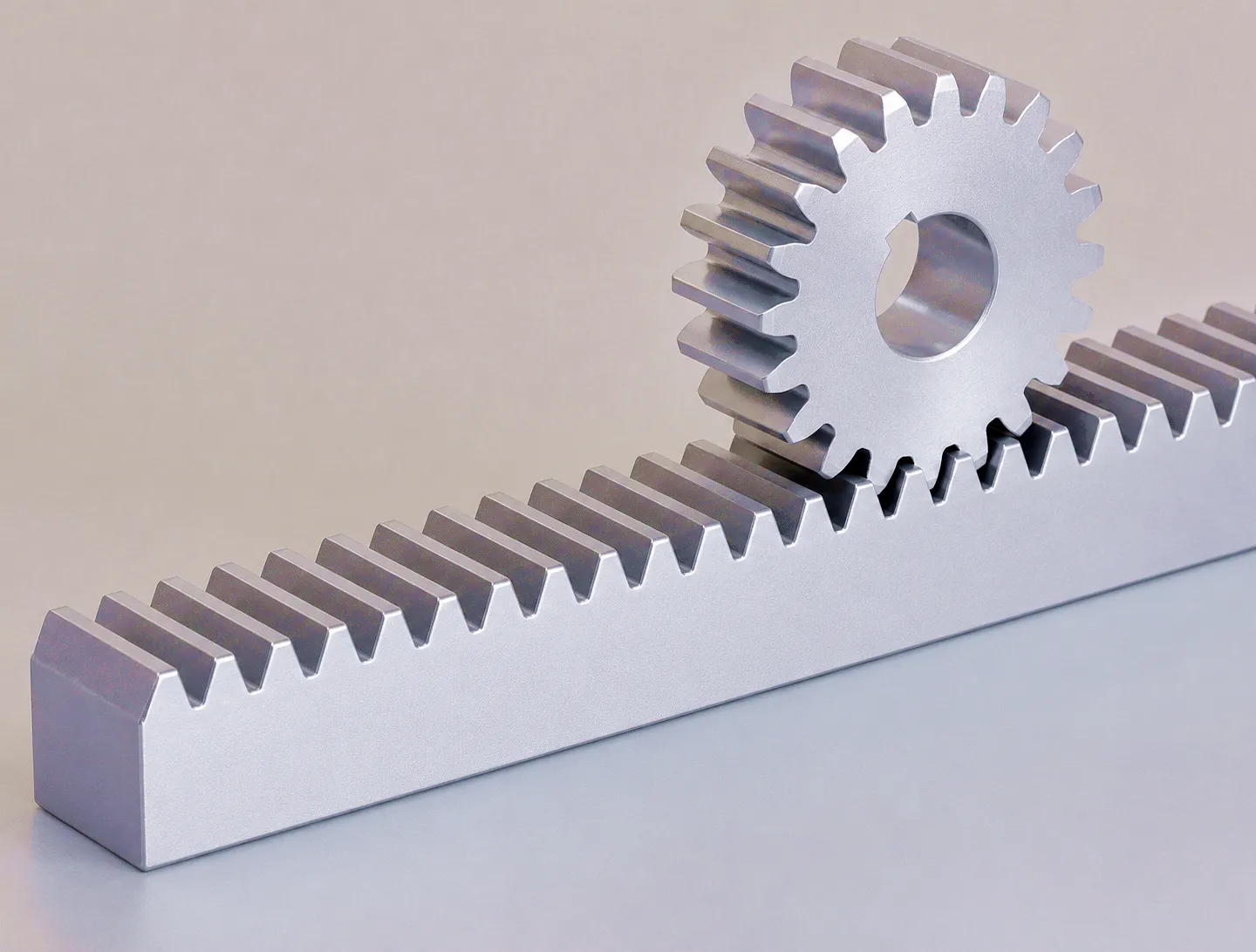
The gear rack and pinion system relies on the involute tooth profile — a curve generated by unwrapping a taut line from a base circle. The involute form ensures that the normal force acting between tooth flanks always passes through the pitch point, maintaining a constant velocity ratio regardless of small centre-distance variations. This property is critical in UK precision machinery, where linear axes on CNC machining centres, gantry robots, and laser-cutting systems must deliver positional repeatability measured in micrometres.
When a pinion meshes with a straight rack, the line of action runs at the pressure angle — typically 20° for most industrial racks — relative to the pitch line. Contact stress peaks along this line, and the rack tooth root experiences bending stress proportional to the tangential force divided by the tooth form factor. As module size increases (i.e., teeth become larger), the lever arm grows and root bending stress rises; as face width increases, the load per unit length drops. Balancing these two variables against the application’s available envelope is the starting point for any rack selection exercise. Helical tooth profiles introduce a third lever: the helix angle, which distributes load over a longer contact line and reduces the stress per unit area — making helical gear racks the preferred choice wherever load density and noise are both concerns.
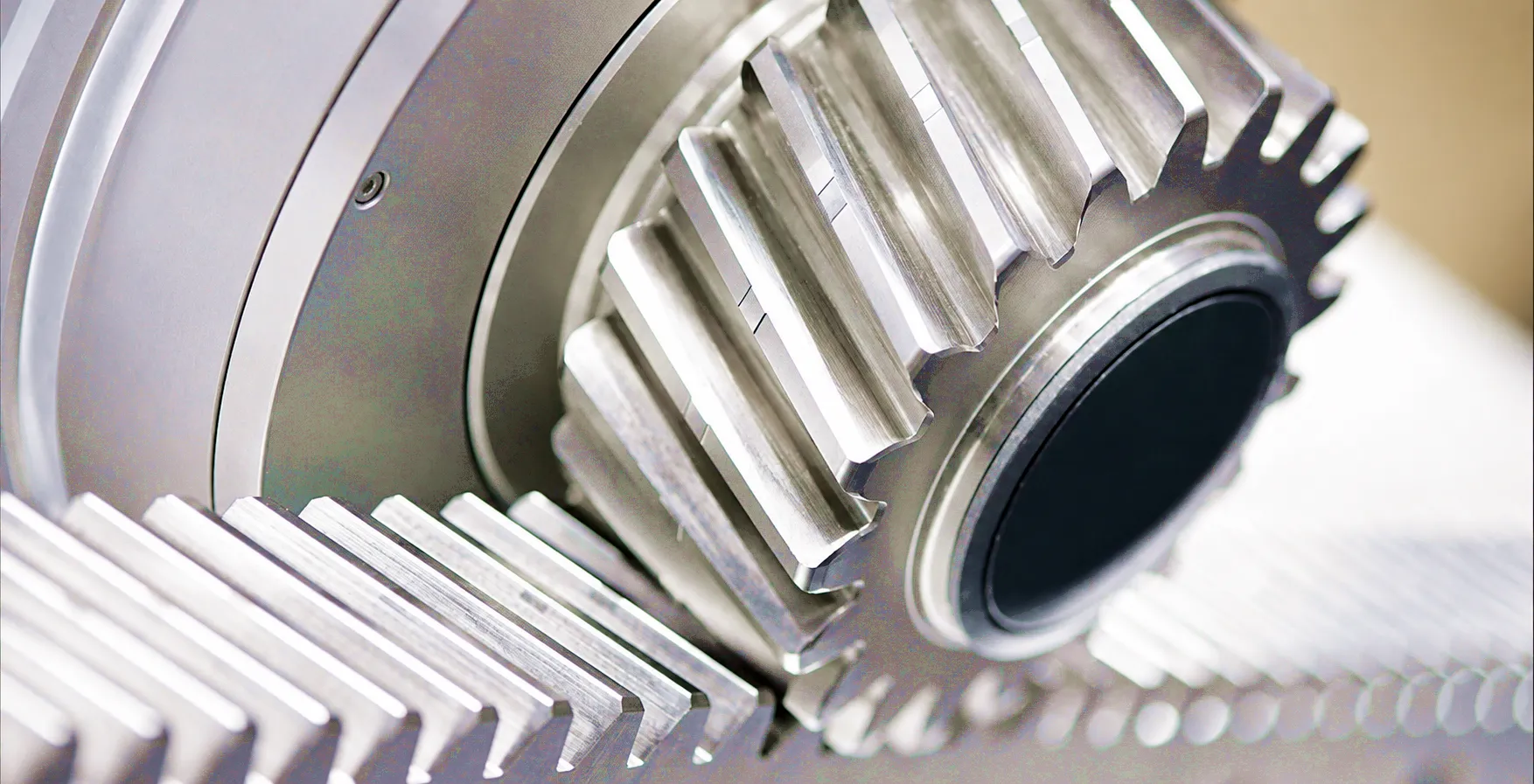
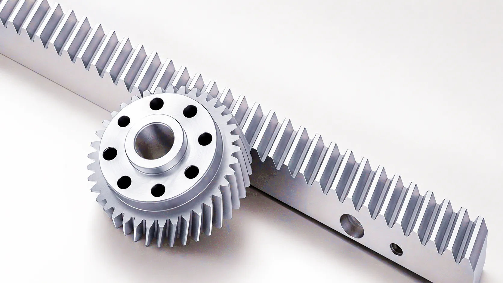
Precision ground helical gear rack — tooth flank geometry and contact line
Spur vs. Helical Gear Rack: Profile Comparison in Practice
Matching tooth geometry to application demands
Straight (Spur) Gear Rack
The spur gear rack carries teeth cut perpendicular to the rack’s longitudinal axis. Contact between the rack tooth and the pinion tooth is instantaneous across the full face width, which means the full tangential load appears and disappears abruptly at each mesh cycle. In practice, this produces an impulse in the drivetrain — audible as a periodic ticking at low speeds and as broadband noise at high pitch-line velocities. Despite this, spur racks remain the dominant choice for many UK industrial applications precisely because of their simplicity: they can be mated with standard spur pinions available from any transmission distributor, require no axial thrust management, and can be butted end-to-end along a long travel axis without a phase-matching step.
For applications where travel speed stays below roughly 1 m/s, load is moderate, and cost is the governing criterion — such as in steel stockholders’ handling systems across the Sheffield and Rotherham area or in agricultural machinery built in the East Midlands — a quality spur rack with a ground or milled tooth profile delivers reliable service with minimal maintenance overhead. The key specification to verify is the tooth root radius: too small a fillet, and fatigue cracks propagate from the root under cyclic bending load; too large, and interference with the mating pinion tooth tip occurs.
Helical Gear Rack
The helical gear rack introduces a helix angle — typically between 10° and 30° — that tilts each tooth relative to the rack axis. As the pinion rotates, contact begins at one end of the tooth and sweeps progressively across the face width, meaning multiple teeth share the load simultaneously. This overlap ratio is directly controlled by the helix angle and face width: a 19° helix angle on a rack with a face width of 40 mm may achieve a contact ratio approaching 2.0, meaning two full tooth pairs are in mesh for a significant portion of each pitch cycle. The effect on noise is dramatic — the load impulse is smoothed out, and high-speed helical rack drives on laser-cutting gantries or injection-moulding machine clamping axes operate almost silently compared with spur equivalents.
Load capacity gains from helical profiling are equally significant. Because the Hertzian contact stress is distributed over a longer instantaneous contact line, the allowable tangential force for a given module and material can be 20% to 40% higher than for a spur rack of the same geometry. For UK machine-builders targeting export markets in Germany’s automotive tier-1 sector or competing on Aerospace North West supply chains, specifying a precision ground helical rack can be the difference between winning a contract and being outspecified by a competitor.
Core Materials: What Goes into a High-Performance Gear Rack
Material selection defines the boundary between adequate and exceptional
● C45 / EN8 Medium Carbon Steel
The workhorse of the gear rack industry. C45 (equivalent to EN8 in the UK standards framework) offers a balanced combination of machinability, hardenability, and cost. In the normalised condition, ultimate tensile strength sits at approximately 570–700 MPa, adequate for medium-duty rack applications. After induction hardening of the tooth flanks to 52–58 HRC, surface contact strength increases substantially while the core remains tough — resisting impact loads common on gantry cranes servicing UK ports and distribution centres in the East Midlands logistics corridor.
● 20CrMnTi / 17CrNiMo6 Case-Hardening Steel
For racks operating at the limits of their load capacity — driving aerospace component positioners in the Bristol corridor or heavy milling axes in Birmingham’s precision machining shops — case-hardening alloy steels provide the optimal combination of a hard, wear-resistant surface layer (0.8–1.5 mm effective case depth) and a tough, ductile core. After carburising, quenching, and tempering, tooth flank hardness reaches 60–64 HRC. The resulting allowable contact stress (sigma_H_lim) of 1550–1650 MPa allows significant reductions in rack module for a given load — an important advantage where installation space is constrained. Profile grinding after heat treatment removes distortion and restores geometry to DIN 5 or better tolerance class.
● 304 / 316 Stainless Steel
Where corrosion resistance matters more than ultimate strength — food processing lines in Yorkshire, pharmaceutical clean-room handling systems, or marine deck equipment for the UK’s offshore energy sector — austenitic stainless steel racks eliminate the need for protective coatings that can chip, contaminate, or fail at elevated temperatures. 316L grade (molybdenum-bearing) provides pitting resistance numbers (PRN) suitable for chloride-rich coastal environments. Hardness is limited by the austenitic matrix (typically 180–220 HV), so stainless racks are reserved for light-duty or medium-duty applications where corrosion resistance is the non-negotiable specification driver.
● Engineering Plastics (POM / Nylon PA66-GF30)
Polymer racks occupy a niche but growing segment of the UK market. Acetal (POM) and glass-filled nylon (PA66-GF30) provide self-lubrication, electrical insulation, and noise dampening in light-duty applications: sliding window actuators in commercial buildings, agricultural feed-line conveyors, and medical scanning platform drives. Maximum allowable surface stress is a fraction of steel equivalents, but for loads under 200 N and speeds below 0.3 m/s, polymer racks provide years of maintenance-free service with zero lubrication cost — a meaningful whole-life cost advantage that UK facilities managers are beginning to appreciate.
Product Advantages: Why Tooth Profile Precision Pays for Itself
Six measurable benefits of specifying a precision-profiled gear rack
Higher Load Capacity per Unit Length
A correctly profiled tooth minimises stress concentration at the root fillet and maximises the contact area over the flank. In helical racks, the extended contact line under load can increase the permissible tangential force by 30–40% compared with an equivalent spur rack. This translates directly into either greater force output from the same rack section, or reduced rack size for the same rated load — both commercially valuable outcomes in compact machine designs.
Reduced Transmission Error and Vibration
Transmission error — the deviation of the driven element from its theoretically perfect position — is the primary source of gear noise and vibration. Precision ground tooth profiles, held to DIN 6 or DIN 5 tolerance class, exhibit transmission errors measured in single-digit micrometres. For UK machine-tool builders, where spindle vibration directly affects surface finish on machined aerospace components, this is a specification-critical parameter that justifies the premium cost of profile-ground racks over hobbed or milled equivalents.
Greater Mechanical Efficiency
Gear rack efficiency is often quoted at 98–99% per mesh — but that figure applies only to well-profiled, correctly lubricated racks operating within their rated load. Poorly profiled teeth with excessive sliding velocity at the tip and root generate frictional heat that degrades lubricant, accelerates wear, and reduces efficiency below 95%. Involute profiling, optimised tip relief, and lead crowning (for helical racks) all contribute to keeping sliding velocity within bounds, maintaining efficiency close to theoretical values even at the extremes of the operating cycle.
Extended Service Life Under Cyclic Loading
UK industrial applications rarely run at constant load; they cycle between light traverse, full-load cutting, acceleration, and deceleration — each phase imposing a different stress state on the rack tooth. Profile accuracy directly affects the stress amplitude at the root (which governs fatigue life) and the surface contact stress (which governs pitting resistance). A precision ground rack with properly specified tip relief and root radius can extend service life by a factor of 3–5 compared with an uncorrected profile, reducing unplanned downtime and maintenance costs across the machine’s operational life.
Compatibility with High-Accuracy Linear Guides
Modern precision racks are increasingly specified as part of an integrated linear axis assembly combining the rack with a profiled linear guide rail — a configuration that constrains the rack’s deflection under off-axis loads and maintains pinion mesh geometry. The tooth profile on the rack must be coordinated with the guide’s preload class and stiffness to avoid introducing parasitic moments. Ever Power’s rectangular guide rail systems are designed in parallel with our rack range to ensure dimensional compatibility and optimised assembly geometry.
Quieter Operation in Noise-Sensitive Environments
Across the UK, noise at work regulations (Control of Noise at Work Regulations 2005) require employers to assess and control noise exposure above 80 dB(A). Rack drives that generate broadband mesh noise can push overall machine noise levels beyond this threshold, creating compliance obligations and potential legal liability. Helical racks with their progressive tooth engagement, combined with profile modifications that eliminate tooth-tip contact shock, reduce mesh-generated noise by typically 6–10 dB(A) compared with unmodified spur equivalents — a difference that can resolve a compliance issue without expensive acoustic enclosures.
Technical Performance Parameters Table
Key specifications across the standard gear rack range
| Parameter | Spur Gear Rack | Helical Gear Rack | Zero Backlash Rack |
|---|---|---|---|
| Module Range | M1 – M12 | M1 – M10 | M1 – M6 |
| Pressure Angle | 20° | 20° (normal) | 20° |
| Helix Angle | 0° | 10° – 30° | 19.5° (typical) |
| Tooth Accuracy Class | DIN 6 – DIN 10 | DIN 5 – DIN 7 | DIN 4 – DIN 5 |
| Surface Hardness (HRC) | 48 – 56 HRC | 52 – 60 HRC | 58 – 64 HRC |
| Permissible Tangential Force | Up to 45,000 N (M8) | Up to 65,000 N (M8) | Up to 22,000 N (M4) |
| Pitch Cumulative Error | ≤ 0.05 mm/300 mm | ≤ 0.025 mm/300 mm | ≤ 0.010 mm/300 mm |
| Standard Length | 500 – 3000 mm | 500 – 2000 mm | 500 – 1500 mm |
| Typical Material | C45 / 42CrMo4 | 20CrMnTi / 17CrNiMo6 | 17CrNiMo6 |
| Finish Process | Hobbing / Milling | Profile Grinding | Profile Grinding + Lapping |
| Max Speed | Up to 1.5 m/s | Up to 5 m/s | Up to 3 m/s |
Industrial Application Scenarios Across the UK
Where tooth profile selection becomes a critical engineering decision
CNC Machining Centres — Birmingham & Coventry Manufacturing Belt
The UK’s West Midlands manufacturing cluster — centred on Birmingham, Coventry, and Wolverhampton — operates one of Europe’s densest concentrations of CNC machining centres producing automotive and aerospace structural components. In these machines, the X and Y linear axes are typically driven by precision helical gear racks mated to ground pinions, operating at pitch-line velocities of 2–4 m/s with acceleration demands of up to 15 m/s². The tooth profile specification for these axes is governed by ISO 1328 accuracy class, with profile tolerances held to ±0.003 mm peak-to-valley error. The rack must also carry the full dynamic load including cutting forces transmitted through the machine structure, requiring careful tooth root analysis under combined bending and torsional loading.
Plasma and Laser Cutting Systems — Sheffield Steel Country
Sheffield’s steel processing and fabrication industry relies on large-format plasma and laser cutting tables to process plate up to 25 mm thick. These gantry systems require rack-and-pinion drives on their long axes (typically 4–20 metres), operating at cutting speeds of 0.5–3 m/s with extremely tight path accuracy demands — a 0.5 mm position error on a 12 m travel produces a visible step in a cut component. Precision helical racks with hardened and ground tooth profiles, joined end-to-end with carefully matched phase splicing, achieve the cumulative pitch error targets needed. The induction hardened helical rack with surface treatment from Ever Power is specifically engineered for these applications, combining surface hardness above 58 HRC with a tight pitch cumulative error tolerance to meet the path accuracy requirements of high-end laser cutting platforms.
Automated Warehouse and Logistics Systems — East Midlands Distribution Hubs
The East Midlands — home to a dense concentration of regional distribution centres serving national retailers and e-commerce fulfilment operations — relies heavily on automated storage and retrieval systems (AS/RS) that use rack-and-pinion drives for vertical and horizontal shuttle movement. These systems run continuously, often 20 hours per day, 365 days per year. The duty cycle demands on the rack drive are severe: the gear rack must maintain pitch accuracy over tens of millions of cycles without adjustment. Tooth profile geometry — particularly tip relief magnitude and root fillet radius — is the primary determinant of fatigue life in these applications. Case-hardened spur racks with DIN 7 accuracy and a surface hardness of 58–62 HRC are the standard specification for the mast drives of unit-load storage and retrieval machines.
Offshore Wind Turbine Pitch and Yaw Systems — North Sea Supply Chain
The UK’s offshore wind sector — with major turbine assembly and servicing operations in Hull, Barrow-in-Furness, and Humberside — represents a demanding application environment for gear racks. Turbine blade pitch control systems use large-module racks (M8–M16) to rotate each blade in response to wind speed, with requirements for reliability in salt-laden air, cyclic load reversal with every rotation, and minimum 25-year service life. The tooth profile for these racks must be analysed under combined bending and axial tooth load (from the helix reaction force), with fatigue calculations carried out to the offshore design standard. Nitrided or case-hardened alloy steel racks with corrosion-resistant surface treatments are the dominant specification for this growing UK industrial sector.
Customer Success Story: Sheffield Precision Fabrication, Heavy Plate Processing
A real-world case study from the UK’s steel fabrication heartland
A mid-sized Sheffield steel fabricator operating three large-format plasma cutting tables contacted Ever Power after experiencing premature rack wear on their primary 12-metre cutting gantry. The installed rack — a milled, unhardened M6 spur rack — had developed visible pitting on the tooth flanks within 18 months of installation, causing position drift and scrapped components. The engineering team had already replaced the rack once under warranty but was now facing the same failure mode on the second installation.
Ever Power’s technical team carried out a remote analysis of the operating parameters: 2.2 m/s peak traverse speed, 450 kg gantry mass, 3 m/s² acceleration, continuous operation across two shifts. The conclusion was clear — the original rack specification was underdesigned for the actual duty cycle, and the milled tooth profile had inadequate surface finish to support hydrodynamic lubrication at the operating pitch-line velocity. The recommended solution was a switch to M6 precision ground helical rack with 19° helix angle, 58–62 HRC flank hardness, and DIN 6 accuracy. A rack-end splicing jig was provided to ensure correct phase alignment across the three 4-metre rack sections.
The replacement racks were delivered DDP to Sheffield within 12 working days. Following installation, position drift was eliminated, and at the 24-month review the racks showed no measurable change in pitch error or flank condition. The fabricator has since standardised on Ever Power helical racks for all three cutting tables and has placed a blanket order covering annual requirements. The total cost of ownership over a 5-year horizon, including elimination of replacement rack purchases and associated downtime, showed a 62% reduction compared with the previous specification.
What Our UK Customers Say
“We moved from a standard milled spur rack to Ever Power’s ground helical specification on all three plasma tables. The difference in machine noise alone was worth the switch — the gantry now runs noticeably quieter at full traverse speed. More importantly, we are 24 months in with no measurable wear, where previously we were replacing racks every 18 months. The precision ground tooth profile has clearly made a significant difference to flank life in our duty cycle.”
— Engineering Manager, Heavy Plate Fabricator, Sheffield, UK
“Ever Power’s technical team understood our axis specification requirements straightaway — we needed a rack-and-rail combination with a pitch cumulative error under 0.015 mm on a 6-metre travel, and they delivered within that tolerance on the very first shipment. The inspection report with individual pitch measurements at every tooth was exactly what our quality team needed for the machine acceptance documentation. The custom mounting-hole pattern they machined to our drawing meant zero fitting issues on site in Birmingham.”
— Mechanical Design Engineer, CNC Machine Builder, Birmingham, UK
“We used Ever Power for a zero-backlash rack specification on a semiconductor inspection platform we were building for a client in Cambridge’s technology park. The positional repeatability requirements were sub-5 micrometre, which is at the edge of what a rack-and-pinion system can achieve. The ground and lapped profile they supplied, combined with their preload pinion recommendation, gave us a measured backlash below 2 micrometres — better than the specification and better than any competing supplier had offered. Delivery was 11 working days from order, which kept our assembly schedule on track.”
— Automation Systems Director, High-Tech Equipment Manufacturer, Cambridge, UK
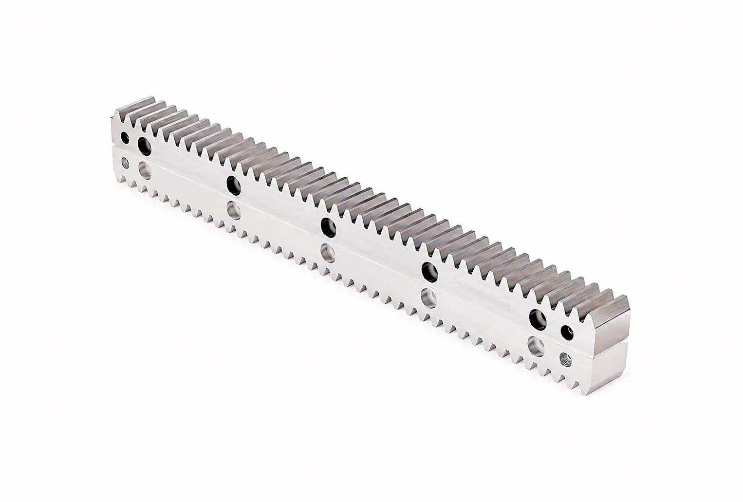
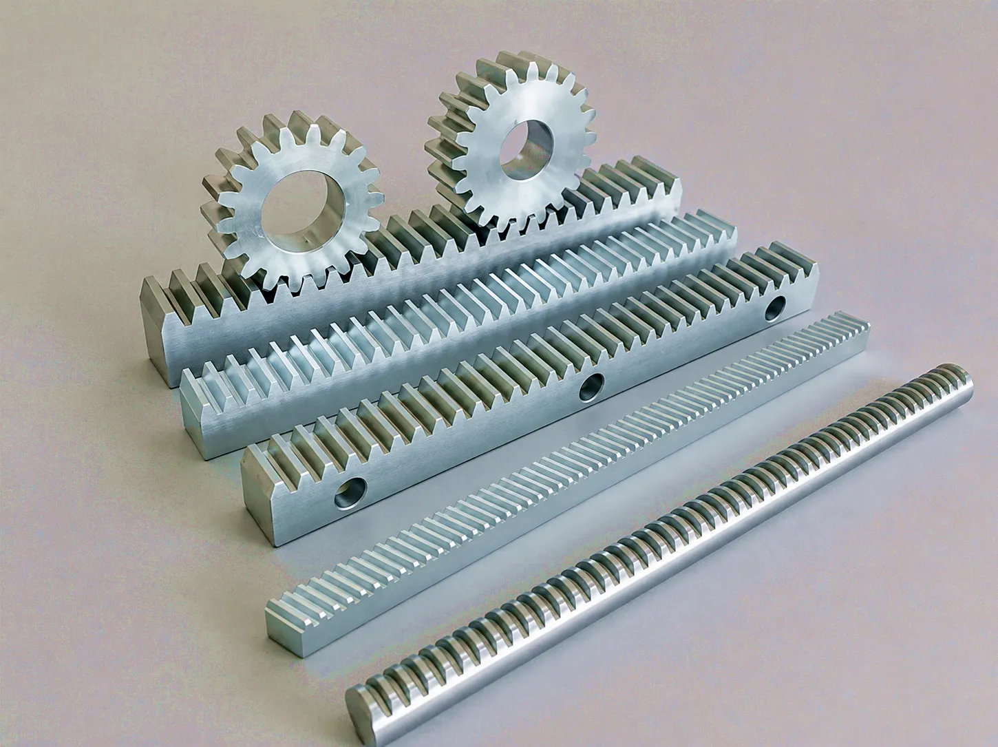
Ever Power precision gear rack range — available in spur, helical, and zero-backlash specifications
Frequently Asked Questions: Gear Rack Selection for UK Industrial Applications
Voice-search-friendly answers from our engineering team
How does the tooth profile of a gear rack affect the maximum load capacity for heavy-duty CNC machines in the UK?
The tooth profile governs three key load limits: the surface contact stress limit (Hertzian stress), the tooth root bending fatigue limit, and the wear-related allowable surface pressure. A precision ground involute profile with the correct pressure angle, tip relief, and root radius maximises all three simultaneously. For heavy-duty CNC machines in the UK — particularly those in the Birmingham and Coventry machining belt — switching from a milled to a ground helical profile can increase the permissible tangential force by 30–40% without changing module or material, directly enabling higher feed forces or allowing a smaller rack cross-section for the same duty.
What is the typical price difference between a standard milled gear rack and a precision ground helical rack when sourcing from a UK supplier?
The cost differential between milled and precision ground helical racks typically ranges from 2.5x to 4x, depending on module, length, and material grade. However, whole-life cost analysis routinely shows the premium paying back within 18–24 months for continuous-duty applications, due to the elimination of early replacement, reduced downtime, and lower lubrication consumption. For an accurate quote on your specific rack size and quantity, contact our sales team directly — we provide transparent pricing with no hidden logistics costs for UK delivery.
Which type of gear rack tooth profile is best suited for laser cutting systems operating in Sheffield’s steel processing industry?
For laser and plasma cutting systems in Sheffield, precision ground helical racks are the standard of choice. The helical tooth profile’s progressive contact engagement reduces pitch impulse — which otherwise manifests as a micro-jog at the cut head, producing a visible mark on the cut edge. The combination of DIN 6 accuracy and 58+ HRC surface hardness provides both path accuracy and the wear resistance needed for continuous multi-shift operation in the abrasive environment of a steel cutting shop. End-to-end splicing with phase-matched joints is essential for long travel axes.
Where can I find a reliable gear rack supplier in the UK who can provide custom tooth profiles and fast delivery for an urgent machine repair?
Ever Power supplies precision gear racks directly to UK customers from stock and on short manufacturing lead times. For urgent machine repair situations, standard precision ground helical and spur racks in common modules (M2 through M8) can typically be delivered to UK addresses within 10–15 working days. Custom profiles — including non-standard pressure angles, special cross-sections, and modified mounting-hole patterns — are available with lead times agreed at the point of order. Contact sales@farm-equipment-parts.com with your drawing or specification for an immediate response from our technical team.
How does a helical gear rack tooth profile improve efficiency and reduce noise in automated warehouse systems across the East Midlands logistics sector?
In automated warehouse systems — where gear racks drive the masts and shuttles of AS/RS installations running near-continuously across the East Midlands distribution hub region — the helical tooth profile’s gradual engagement curve reduces the periodic impulse load that causes spur racks to generate broadband mechanical noise. In practice, helical rack systems in AS/RS applications operate 6–10 dB(A) quieter than spur equivalents, which can be the deciding factor in securing planning permission for a new facility in a semi-urban location. The efficiency gain — typically 0.5–1.5% over the full duty cycle — may seem small per axis but accumulates to meaningful energy cost savings across a large installation running 7,000+ hours per year.
When should I specify a zero-backlash gear rack instead of a standard precision ground rack for a high-accuracy application in the UK aerospace industry?
A zero-backlash rack is warranted when positional repeatability requirements fall below approximately 10 micrometres and the drive system undergoes frequent motion reversal — both of which are common in aerospace inspection jigs, coordinate measuring machine drives, and precision assembly fixtures used by UK aerospace supply chain firms in the Bristol, Derby, and Filton areas. Standard precision ground racks achieve backlash of 20–60 micrometres depending on fit and tolerance class; zero-backlash racks using split-pinion or spring-loaded preload mechanisms reduce this to under 5 micrometres, enabling closed-loop axis performance comparable to a ball screw at longer travel lengths than ball screw systems can practically achieve.
Ready to Specify the Right Gear Rack for Your Application?
Send us your application parameters, drawing, or performance requirements. Our technical team will respond within one business day with a recommendation and quotation.
Get a Quote: sales@farm-equipment-parts.com
edit by gzl