Tag Archives: manufacturer sprocket

China manufacturer Alloy Steel/Stainless Steel Made-to-Order ANSI or DIN Driving Sprocket Motorcycle Parts with Best Sales

Product Description

Alloy Steel/Stainless Steel Made-to-order ANSI OR DIN Driving Sprocket Motorcycle Parts
 

Product Description


1. Produce strictly in accordance with ANSI or DIN standard dimension
2. Material: C45 steel / Stainless Steel 304 & 316
3. Standard: ANSI, DIN, JINS, ISO, Standard America or customer drawing
4. Pilot bore, finished bore, taper bore and special bore.
5. Bright surface and high precision
6. Advanced heat treatment and surface treatment craft
7. Best quality and competitive price.
8. Welcome OEM / ODM 
9. Application: Mining machinery, construction machinery, oil machinery, etc
10. Processing equipment: Hobbing machine, Slotting machine, CNC lathes and other equipment.
11. Sprocket models: Contains special sprocket according to customer’s drawings, standard sprocket (American standard and metric).

Features:Sprocket / Gear / Sand Casting / Steel sand casting / Lost wax casting and accessories / Investment casting

Materials: Carbon steel, alloy steel, stainless steel, ductile iron, gray iron, high chromium iron
 

Product name  Ball Bearing Idler Sprocket (05BB, 06BB, 08BB )
Materials Available  1. Stainless Steel: SS304, SS316, etc
2. Alloy Steel: C45 ,45Mn, 42CrMo, 20CrMo, etc
3. OEM according to your request
Surface Treatment Heat treatment , Quenching treatment, High frequency normalizing treatment, Polishing, Electrophoresis paint processing, Anodic oxidation treatment, etc
Characteristic Fire Resistant, Oil Resistant, Heat Resistant, CZPT resistance, Oxidative resistance, Corrosion resistance, etc
Design criterion ISO DIN ANSI & Customer Drawings
Size Customer Drawings & ISO standard 
Application Industrial transmission equipment
Package Wooden Case / Container and pallet, or made-to-order
Certificate ISO9001: 2008 
Advantage Quality first, Service first, Competitive price, Fast delivery
Delivery Time 20 days for samples. 45 days for official order.


Detailed Photos

View more products,please click here…
 

Company Profile


How to use the pulley system

Using a pulley system is a great way to move things around your home, but how do you use a pulley system? Let’s look at the basic equations that describe a pulley system, the types of pulleys, and some safety considerations when using pulleys. Here are some examples. Don’t worry, you’ll find all the information you need in 1 place!
pulley

Basic equations of pulley systems

The pulley system consists of pulleys and chords. When the weight of the load is pulled through the rope, it slides through the groove and ends up on the other side. When the weight moves, the applied force must travel nx distance. The distance is in meters. If there are 4 pulleys, the distance the rope will travel will be 2×24. If there are n pulleys, the distance traveled by the weight will be 2n – 1.
The mechanical advantage of the pulley system increases with distance. The greater the distance over which the force is applied, the greater the leverage of the system. For example, if a set of pulleys is used to lift the load, 1 should be attached to the load and the other to the stand. The load itself does not move. Therefore, the distance between the blocks must be shortened, and the length of the line circulating between the pulleys must be shortened.
Another way to think about the acceleration of a pulley system is to think of ropes and ropes as massless and frictionless. Assuming the rope and pulley are massless, they should have the same magnitude and direction of motion. However, in this case the quality of the string is a variable that is not overdone. Therefore, the tension vector on the block is labeled with the same variable name as the pulley.
The calculation of the pulley system is relatively simple. Five mechanical advantages of the pulley system can be found. This is because the number of ropes supporting the load is equal to the force exerted on the ropes. When the ropes all move in the same direction, they have 2 mechanical advantages. Alternatively, you can use a combination of movable and fixed pulleys to reduce the force.
When calculating forces in a pulley system, you can use Newton’s laws of motion. Newton’s second law deals with acceleration and force. The fourth law tells us that tension and gravity are in equilibrium. This is useful if you need to lift heavy objects. The laws of motion help with calculations and can help you better understand pulley systems.
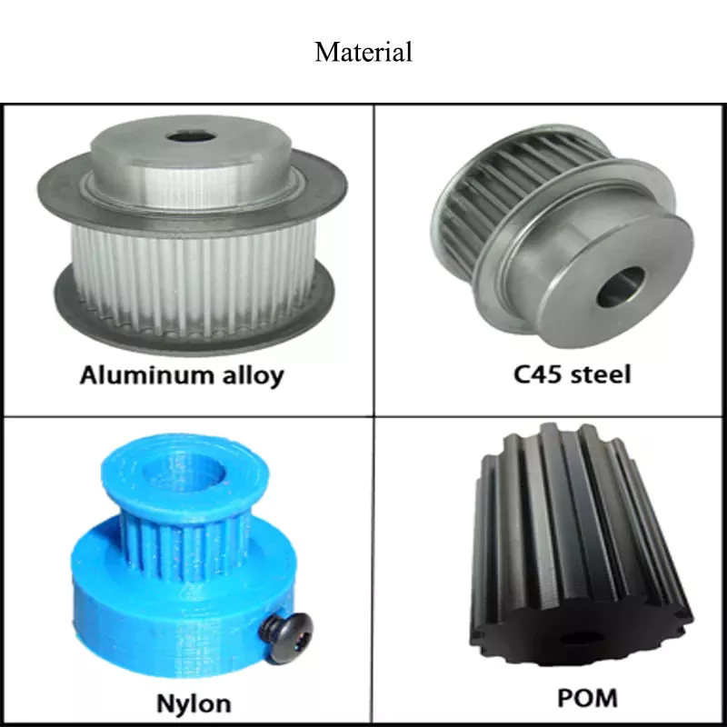
pulley

Types of pulleys

Different types of pulleys are commonly used for various purposes, including lifting. Some pulleys are flexible, which means they can move freely around a central axis and can change the direction of force. Some are fixed, such as hinges, and are usually used for heavier loads. Others are movable, such as coiled ropes. Whatever the purpose, pulleys are very useful in raising and lowering objects.
Pulleys are common in many different applications, from elevators and cargo lift systems to lights and curtains. They are also used in sewing machine motors and sliding doors. Garage and patio doors are often equipped with pulleys. Rock climbers use a pulley system to climb rocks safely. These pulley systems have different types of pinions that allow them to balance weight and force direction.
The most common type of pulley is the pulley pulley system. The pulley system utilizes mechanical advantages to lift weight. Archimedes is thought to have discovered the pulley around 250 BC. in ancient Sicily. Mesopotamians also used pulleys, they used ropes to lift water and windmills. Pulley systems can even be found at Stonehenge.
Another type of pulley is called a compound pulley. It consists of a set of parallel pulleys that increase the force required to move large objects. This type is most commonly used in rock climbing and sailing, while composite pulleys can also be found in theater curtains. If you’re wondering the difference between these 2 types of pulleys, here’s a quick overview:

Mechanical Advantages of Pulley Systems

Pulley systems offer significant mechanical advantages. The ability of the system to reduce the effort required to lift weights increases with the number of rope loops. This advantage is proportional to the number of loops in the system. If the rope had only 1 loop, then a single weight would require the same amount of force to pull. But by adding extra cycles, the force required will be reduced.
The pulley system has the advantage of changing the direction of the force. This makes it easier to move heavy objects. They come in both fixed and mobile. Pulleys are used in many engineering applications because they can be combined with other mechanisms. If you want to know what a pulley can do, read on! Here are some examples. Therefore, you will understand how they are used in engineering.
Single-acting pulleys do not change direction, but compound pulleys do. Their mechanical advantage is six. The compound pulley system consists of a movable pulley and a fixed pulley. The mechanical advantage of the pulley system increases as the number of movable wheels decreases. So if you have 2 wheels, you need twice as much force to lift the same weight because you need a movable pulley.
The mechanical advantage of a pulley system can be maximized by adding more pulleys or rope lengths. For example, if you have a single pulley system, the mechanical advantage is 1 of the smallest. By using 2 or 3 pulleys, up to 5 times the mechanical advantage can be achieved. You can also gain up to 10 times the mechanical advantage by using multiple pulley systems.
The use of a single movable pulley system also adds to the mechanical advantage of the pulley system. In this case, you don’t have to change the direction of the force to lift the weight. In contrast, a movable pulley system requires you to move the rope farther to generate the same force. Using a compound pulley system allows you to lift heavy loads with ease.
pulley

Safety Issues When Using Pulley Systems

Pulleys have an incredibly unique structure, consisting of a disc with a groove in the middle and a shaft running through it. A rope or cord is attached to 1 end of a pulley that turns when force is applied. The other end of the rope is attached to the load. This mechanical advantage means that it is much easier to pull an object using the pulley system than to lift the same object by hand.
Although pulley systems are a common part of many manufacturing processes, some employers do not train their workers to use them properly or install protection to prevent injury. It is important to wear proper PPE and follow standard laboratory safety practices during pulley system activities. Make sure any support structures are strong enough to handle the weight and weight of the rope or rope. If you do fall, be sure to contact your employer immediately.

China manufacturer Alloy Steel/Stainless Steel Made-to-Order ANSI or DIN Driving Sprocket Motorcycle Parts     with Best SalesChina manufacturer Alloy Steel/Stainless Steel Made-to-Order ANSI or DIN Driving Sprocket Motorcycle Parts     with Best Sales

China wholesaler Manufacturer direct sales High Precision   Sprocket auto parts Machinery parts with Hot selling

Product Description

Product Description


Advantage Products


Application


Agriculture Mining
Engineering Chemical machinery
Textile Plastic
Dyeing and fining Other industries

Company Profile

About Us

Focus on a variety of industries
Provide maintenance solutions
Optimize customer inventory and reduce cost

Established in 2012, HangZhou Granville is a branch of the Granville Group. With our experience, competitive prices and excellent service, we have won the praise of our customers. Our business involves standard and special industrial parts, automotive parts and construction machinery parts required for a variety of different industrial applications.
Our main products include
Bearing series :
ball bearings, deep groove ball bearings, self-aligning ball bearings, angularcontact ball bearings, cylindrical roller bearing, tapered roller bearings, thrust ball bearings, thrust rollerbearings, needle bearings, spherical bearings, joint bearings, pillow blocks, linear bearings, etc.
Accessories series:Automotive Spare Parts,Seals & O-rings ,Power transmission parts Chain and Sprocket
Our products are mainly exported to Europe, America, Middle East, Southeast Asia, India, Pakistan, Bangladesh, Singapore, Korea and other countries around the world. We have a large number of products in stock, which can be delivered with high efficiency in the shortest possible time to solve your matching problems in time. In addition, we have reliable quality and quantity of products to offer. We adhere to the principle of win-win situation and insist on “providing comprehensive quality products and best reputation” to provide excellent services to our customers.

What We Do

Comprehensive product range:
– Bearings
– Oil seals, Transmission belt
– Chain and Sprocket
– Hub assembly & Wheel bearings
– Coupling, castings
– Linear motion

Packaging & Shipping


Our Advantages

1. We have the most advanced bearing process equipment, CNC automatic facilities, and testing instruments.
2. We manufacture ball bearings and mounted bearing units, and also provide a strong full range of products, including electric motors and components One-stop partnerships products from our audited supply chain.
3. All products are manufactured exclusively by companies with ISO 9001:2008 certified Quality Systems which use state-of-the-art machines. The quality path starts from the beginning to deliver and goods’ quality trackable

Our Values
Behavior-based, service-oriented, focused on results and committed to continuous improvement

Advantage Manufacturing Processes and Quality Control:

01Heat Treatment
02 Centerless Grinding Machine 11200 (most advanced)
03 Automatic Production Lines for Raceway
04 Automatic Production Lines for Raceway
05 Ultrasonic Cleaning of Rings
06 Automatic Assembly
07 Ultrasonic Cleaning of Bearings
08 Automatic Greasing, Seals Pressing
09Measurement of Bearing Vibration (Acceleration)
10 Measurement of Bearing Vibration (Speed)
11 Laser Marking
12 Automatic Packing

After Sales Service

  1. Optimize customer inventory and reduce cost
  2. Provide maintenance solutions

Quality Warranty

Granville as a manufacturer of high quality products, guarantees compliance with the highest standards relative to the use of the best steel quality in the production process, the highest standards in the design of contact surfaces, as well as the most efficient packing and lubrication of parts. From material coming, quality control through all processes. Except interal test, goods to third party inspection if required. After the center of inspection and experiment being founded, effective methods of inspecting all kinds of raw materials are mastered and then the reliability of bearings is ensured. One of our main objectives is the continued improvement in the quality of our products and processes, in pursuit of which we obtained ISO certification 9001:2008 and TS16949. 

Factory


FAQ

Q1.Can you accept OEM and customization?

A: Yes. We can customize it according to the samples and drawings you provide.

Q2.Do you keep a stock of these things?
A: In stocks

Q3.Can you provide samples free of charge?
A: Yes. We can provide samples free of charge. But the freight is paid by the customer.

Q4.What’s the delivery date?
A: The delivery time of sample orders is 3 working days.The bulk orders are 5-10 working days.

Q5: Why your price is higher than others?
A: Price = quality . We firmly believe that by the quality of the customer is always get more reliable than on price . So we insist on doing high-quality products.

Q6:What kind of transport do you have ?
A: According to the weight,we will choose the most appropriate mode of transport for you. Our freight forwarding is efficient and cheap

Analytical Approaches to Estimating Contact Pressures in Spline Couplings

A spline coupling is a type of mechanical connection between 2 rotating shafts. It consists of 2 parts – a coupler and a coupling. Both parts have teeth which engage and transfer loads. However, spline couplings are typically over-dimensioned, which makes them susceptible to fatigue and static behavior. Wear phenomena can also cause the coupling to fail. For this reason, proper spline coupling design is essential for achieving optimum performance.
splineshaft

Modeling a spline coupling

Spline couplings are becoming increasingly popular in the aerospace industry, but they operate in a slightly misaligned state, causing both vibrations and damage to the contact surfaces. To solve this problem, this article offers analytical approaches for estimating the contact pressures in a spline coupling. Specifically, this article compares analytical approaches with pure numerical approaches to demonstrate the benefits of an analytical approach.
To model a spline coupling, first you create the knowledge base for the spline coupling. The knowledge base includes a large number of possible specification values, which are related to each other. If you modify 1 specification, it may lead to a warning for violating another. To make the design valid, you must create a spline coupling model that meets the specified specification values.
After you have modeled the geometry, you must enter the contact pressures of the 2 spline couplings. Then, you need to determine the position of the pitch circle of the spline. In Figure 2, the centre of the male coupling is superposed to that of the female spline. Then, you need to make sure that the alignment meshing distance of the 2 splines is the same.
Once you have the data you need to create a spline coupling model, you can begin by entering the specifications for the interface design. Once you have this data, you need to choose whether to optimize the internal spline or the external spline. You’ll also need to specify the tooth friction coefficient, which is used to determine the stresses in the spline coupling model 20. You should also enter the pilot clearance, which is the clearance between the tip 186 of a tooth 32 on 1 spline and the feature on the mating spline.
After you have entered the desired specifications for the external spline, you can enter the parameters for the internal spline. For example, you can enter the outer diameter limit 154 of the major snap 54 and the minor snap 56 of the internal spline. The values of these parameters are displayed in color-coded boxes on the Spline Inputs and Configuration GUI screen 80. Once the parameters are entered, you’ll be presented with a geometric representation of the spline coupling model 20.

Creating a spline coupling model 20

The spline coupling model 20 is created by a product model software program 10. The software validates the spline coupling model against a knowledge base of configuration-dependent specification constraints and relationships. This report is then input to the ANSYS stress analyzer program. It lists the spline coupling model 20’s geometric configurations and specification values for each feature. The spline coupling model 20 is automatically recreated every time the configuration or performance specifications of the spline coupling model 20 are modified.
The spline coupling model 20 can be configured using the product model software program 10. A user specifies the axial length of the spline stack, which may be zero, or a fixed length. The user also enters a radial mating face 148, if any, and selects a pilot clearance specification value of 14.5 degrees or 30 degrees.
A user can then use the mouse 110 to modify the spline coupling model 20. The spline coupling knowledge base contains a large number of possible specification values and the spline coupling design rule. If the user tries to change a spline coupling model, the model will show a warning about a violation of another specification. In some cases, the modification may invalidate the design.
In the spline coupling model 20, the user enters additional performance requirement specifications. The user chooses the locations where maximum torque is transferred for the internal and external splines 38 and 40. The maximum torque transfer location is determined by the attachment configuration of the hardware to the shafts. Once this is selected, the user can click “Next” to save the model. A preview of the spline coupling model 20 is displayed.
The model 20 is a representation of a spline coupling. The spline specifications are entered in the order and arrangement as specified on the spline coupling model 20 GUI screen. Once the spline coupling specifications are entered, the product model software program 10 will incorporate them into the spline coupling model 20. This is the last step in spline coupling model creation.
splineshaft

Analysing a spline coupling model 20

An analysis of a spline coupling model consists of inputting its configuration and performance specifications. These specifications may be generated from another computer program. The product model software program 10 then uses its internal knowledge base of configuration dependent specification relationships and constraints to create a valid three-dimensional parametric model 20. This model contains information describing the number and types of spline teeth 32, snaps 34, and shoulder 36.
When you are analysing a spline coupling, the software program 10 will include default values for various specifications. The spline coupling model 20 comprises an internal spline 38 and an external spline 40. Each of the splines includes its own set of parameters, such as its depth, width, length, and radii. The external spline 40 will also contain its own set of parameters, such as its orientation.
Upon selecting these parameters, the software program will perform various analyses on the spline coupling model 20. The software program 10 calculates the nominal and maximal tooth bearing stresses and fatigue life of a spline coupling. It will also determine the difference in torsional windup between an internal and an external spline. The output file from the analysis will be a report file containing model configuration and specification data. The output file may also be used by other computer programs for further analysis.
Once these parameters are set, the user enters the design criteria for the spline coupling model 20. In this step, the user specifies the locations of maximum torque transfer for both the external and internal spline 38. The maximum torque transfer location depends on the configuration of the hardware attached to the shafts. The user may enter up to 4 different performance requirement specifications for each spline.
The results of the analysis show that there are 2 phases of spline coupling. The first phase shows a large increase in stress and vibration. The second phase shows a decline in both stress and vibration levels. The third stage shows a constant meshing force between 300N and 320N. This behavior continues for a longer period of time, until the final stage engages with the surface.
splineshaft

Misalignment of a spline coupling

A study aimed to investigate the position of the resultant contact force in a spline coupling engaging teeth under a steady torque and rotating misalignment. The study used numerical methods based on Finite Element Method (FEM) models. It produced numerical results for nominal conditions and parallel offset misalignment. The study considered 2 levels of misalignment – 0.02 mm and 0.08 mm – with different loading levels.
The results showed that the misalignment between the splines and rotors causes a change in the meshing force of the spline-rotor coupling system. Its dynamics is governed by the meshing force of splines. The meshing force of a misaligned spline coupling is related to the rotor-spline coupling system parameters, the transmitting torque, and the dynamic vibration displacement.
Despite the lack of precise measurements, the misalignment of splines is a common problem. This problem is compounded by the fact that splines usually feature backlash. This backlash is the result of the misaligned spline. The authors analyzed several splines, varying pitch diameters, and length/diameter ratios.
A spline coupling is a two-dimensional mechanical system, which has positive backlash. The spline coupling is comprised of a hub and shaft, and has tip-to-root clearances that are larger than the backlash. A form-clearance is sufficient to prevent tip-to-root fillet contact. The torque on the splines is transmitted via friction.
When a spline coupling is misaligned, a torque-biased thrust force is generated. In such a situation, the force can exceed the torque, causing the component to lose its alignment. The two-way transmission of torque and thrust is modeled analytically in the present study. The analytical approach provides solutions that can be integrated into the design process. So, the next time you are faced with a misaligned spline coupling problem, make sure to use an analytical approach!
In this study, the spline coupling is analyzed under nominal conditions without a parallel offset misalignment. The stiffness values obtained are the percentage difference between the nominal pitch diameter and load application diameter. Moreover, the maximum percentage difference in the measured pitch diameter is 1.60% under a torque of 5000 N*m. The other parameter, the pitch angle, is taken into consideration in the calculation.

China wholesaler Manufacturer direct sales High Precision   Sprocket auto parts Machinery parts     with Hot sellingChina wholesaler Manufacturer direct sales High Precision   Sprocket auto parts Machinery parts     with Hot selling