Product Description
Excellent powder metallurgy parts metallic sintered parts
We could offer various powder metallurgy parts including iron based and copper based with top quality and cheapest price, please only send the drawing or sample to us, we will according to customer’s requirement to make it. if you are interested in our product, please do not hesitate to contact us, we would like to offer the top quality and best service for you. thank you!
How do We Work with Our Clients
1. For a design expert or a big company with your own engineering team: we prefer to receive a fully RFQ pack from you including drawing, 3D model, quantity, pictures;
2. For a start-up company owner or green hand for engineering: just send an idea that you want to try, you don’t even need to know what casting is;
3. Our sales will reply you within 24 hours to confirm further details and give the estimated quote time;
4. Our engineering team will evaluate your inquiry and provide our offer within next 1~3 working days.
5. We can arrange a technical communication meeting with you and our engineers together anytime if required.
| Place of origin: | Jangsu,China |
| Type: | Powder metallurgy sintering |
| Spare parts type: | Powder metallurgy parts |
| Machinery Test report: | Provided |
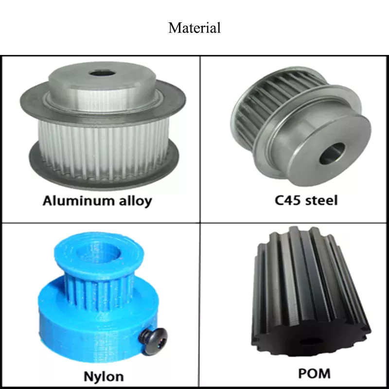
| Material: | Iron,stainless,steel,copper |
| Key selling points: | Quality assurance |
| Mould type: | Tungsten steel |
| Material standard: | MPIF 35,DIN 3571,JIS Z 2550 |
| Application: | Small home appliances,Lockset,Electric tool, automobile, |
| Brand Name: | OEM SERVICE |
| Plating: | Customized |
| After-sales Service: | Online support |
| Processing: | Powder Metallurgr,CNC Machining |
| Powder Metallurgr: | High frequency quenching, oil immersion |
| Quality Control: | 100% inspection |
The Advantage of Powder Metallurgy Process
1. Cost effective
The final products can be compacted with powder metallurgy method ,and no need or can shorten the processing of machine .It can save material greatly and reduce the production cost .
2. Complex shapes
Powder metallurgy allows to obtain complex shapes directly from the compacting tooling ,without any machining operation ,like teeth ,splines ,profiles ,frontal geometries etc.
3. High precision
Achievable tolerances in the perpendicular direction of compacting are typically IT 8-9 as sintered,improvable up to IT 5-7 after sizing .Additional machining operations can improve the precision .
4. Self-lubrication
The interconnected porosity of the material can be filled with oils ,obtaining then a self-lubricating bearing :the oil provides constant lubrication between bearing and shaft ,and the system does not need any additional external lubricant .
5. Green technology
The manufacturing process of sintered components is certified as ecological ,because the material waste is very low ,the product is recyclable ,and the energy efficiency is good because the material is not molten.
FAQ
Q1: What is the type of payment?
A: Usually you should prepay 50% of the total amount. The balance should be pay off before shipment.
Q2: How to guarantee the high quality?
A: 100% inspection. We have Carl Zeiss high-precision testing equipment and testing department to make sure every product of size,appearance and pressure test are good.
Q3: How long will you give me the reply?
A: we will contact you in 12 hours as soon as we can.
Q4. How about your delivery time?
A: Generally, it will take 25 to 35 days after receiving your advance payment. The specific delivery time depends on the items and the quantity of your order. and if the item was non standard, we have to consider extra 10-15days for tooling/mould made.
Q5. Can you produce according to the samples or drawings?
A: Yes, we can produce by your samples or technical drawings. We can build the molds and fixtures.
Q6: How about tooling Charge?
A: Tooling charge only charge once when first order, all future orders would not charge again even tooling repair or under maintance.
Q7: What is your sample policy?
A: We can supply the sample if we have ready parts in stock, but the customers have to pay the sample cost and the courier cost.
Q8: How do you make our business long-term and good relationship?
A: 1. We keep good quality and competitive price to ensure our customers benefit ;
2. We respect every customer as our friend and we sincerely do business and make friends with them, no matter where they come from.
Helical, Straight-Cut, and Spiral-Bevel Gears
If you are planning to use bevel gears in your machine, you need to understand the differences between Helical, Straight-cut, and Spiral bevel gears. This article will introduce you to these gears, as well as their applications. The article will also discuss the benefits and disadvantages of each type of bevel gear. Once you know the differences, you can choose the right gear for your machine. It is easy to learn about spiral bevel gears.
Spiral bevel gear
Spiral bevel gears play a critical role in the aeronautical transmission system. Their failure can cause devastating accidents. Therefore, accurate detection and fault analysis are necessary for maximizing gear system efficiency. This article will discuss the role of computer aided tooth contact analysis in fault detection and meshing pinion position errors. You can use this method to detect problems in spiral bevel gears. Further, you will learn about its application in other transmission systems.
Spiral bevel gears are designed to mesh the gear teeth more slowly and appropriately. Compared to straight bevel gears, spiral bevel gears are less expensive to manufacture with CNC machining. Spiral bevel gears have a wide range of applications and can even be used to reduce the size of drive shafts and bearings. There are many advantages to spiral bevel gears, but most of them are low-cost.
This type of bevel gear has 3 basic elements: the pinion-gear pair, the load machine, and the output shaft. Each of these is in torsion. Torsional stiffness accounts for the elasticity of the system. Spiral bevel gears are ideal for applications requiring tight backlash monitoring and high-speed operations. CZPT precision machining and adjustable locknuts reduce backlash and allow for precise adjustments. This reduces maintenance and maximizes drive lifespan.
Spiral bevel gears are useful for both high-speed and low-speed applications. High-speed applications require spiral bevel gears for maximum efficiency and speed. They are also ideal for high-speed and high torque, as they can reduce rpm without affecting the vehicle’s speed. They are also great for transferring power between 2 shafts. Spiral bevel gears are widely used in automotive gears, construction equipment, and a variety of industrial applications.
Hypoid bevel gear
The Hypoid bevel gear is similar to the spiral bevel gear but differs in the shape of the teeth and pinion. The smallest ratio would result in the lowest gear reduction. A Hypoid bevel gear is very durable and efficient. It can be used in confined spaces and weighs less than an equivalent cylindrical gear. It is also a popular choice for high-torque applications. The Hypoid bevel gear is a good choice for applications requiring a high level of speed and torque.
The Hypoid bevel gear has multiple teeth that mesh with each other at the same time. Because of this, the gear transmits torque with very little noise. This allows it to transfer a higher torque with less noise. However, it must be noted that a Hypoid bevel gear is usually more expensive than a spiral bevel gear. The cost of a Hypoid bevel gear is higher, but its benefits make it a popular choice for some applications.
A Hypoid bevel gear can be made of several types. They may differ in the number of teeth and their spiral angles. In general, the smaller hypoid gear has a larger pinion than its counterpart. This means that the hypoid gear is more efficient and stronger than its bevel cousin. It can even be nearly silent if it is well lubricated. Once you’ve made the decision to get a Hypoid bevel gear, be sure to read up on its benefits.
Another common application for a Hypoid bevel gear is in automobiles. These gears are commonly used in the differential in automobiles and trucks. The torque transfer characteristics of the Hypoid gear system make it an excellent choice for many applications. In addition to maximizing efficiency, Hypoid gears also provide smoothness and efficiency. While some people may argue that a spiral bevel gear set is better, this is not an ideal solution for most automobile assemblies.
Helical bevel gear
Compared to helical worm gears, helical bevel gears have a small, compact housing and are structurally optimized. They can be mounted in various ways and feature double chamber shaft seals. In addition, the diameter of the shaft and flange of a helical bevel gear is comparable to that of a worm gear. The gear box of a helical bevel gear unit can be as small as 1.6 inches, or as large as 8 cubic feet.
The main characteristic of helical bevel gears is that the teeth on the driver gear are twisted to the left and the helical arc gears have a similar design. In addition to the backlash, the teeth of bevel gears are twisted in a clockwise and counterclockwise direction, depending on the number of helical bevels in the bevel. It is important to note that the tooth contact of a helical bevel gear will be reduced by about 10 to 20 percent if there is no offset between the 2 gears.
In order to create a helical bevel gear, you need to first define the gear and shaft geometry. Once the geometry has been defined, you can proceed to add bosses and perforations. Then, specify the X-Y plane for both the gear and the shaft. Then, the cross section of the gear will be the basis for the solid created after revolution around the X-axis. This way, you can make sure that your gear will be compatible with the pinion.
The development of CNC machines and additive manufacturing processes has greatly simplified the manufacturing process for helical bevel gears. Today, it is possible to design an unlimited number of bevel gear geometry using high-tech machinery. By utilizing the kinematics of a CNC machine center, you can create an unlimited number of gears with the perfect geometry. In the process, you can make both helical bevel gears and spiral bevel gears.
Straight-cut bevel gear
A straight-cut bevel gear is the easiest to manufacture. The first method of manufacturing a straight bevel gear was to use a planer with an indexing head. Later, more efficient methods of manufacturing straight bevel gears were introduced, such as the Revacycle system and the Coniflex system. The latter method is used by CZPT. Here are some of the main benefits of using a straight-cut bevel gear.
A straight-cut bevel gear is defined by its teeth that intersect at the axis of the gear when extended. Straight-cut bevel gears are usually tapered in thickness, with the outer part being larger than the inner portion. Straight-cut bevel gears exhibit instantaneous lines of contact, and are best suited for low-speed, static-load applications. A common application for straight-cut bevel gears is in the differential systems of automobiles.
After being machined, straight-cut bevel gears undergo heat treatment. Case carburizing produces gears with surfaces of 60-63 Rc. Using this method, the pinion is 3 Rc harder than the gear to equalize wear. Flare hardening, flame hardening, and induction hardening methods are rarely used. Finish machining includes turning the outer and inner diameters and special machining processes.
The teeth of a straight-cut bevel gear experience impact and shock loading. Because the teeth of both gears come into contact abruptly, this leads to excessive noise and vibration. The latter limits the speed and power transmission capacity of the gear. On the other hand, a spiral-cut bevel gear experiences gradual but less-destructive loading. It can be used for high-speed applications, but it should be noted that a spiral-cut bevel gear is more complicated to manufacture.
Spur-cut bevel gear
CZPT stocks bevel gears in spiral and straight tooth configurations, in a range of ratios from 1.5 to five. They are also highly remachinable except for the teeth. Spiral bevel gears have a low helix angle and excellent precision properties. CZPT stock bevel gears are manufactured using state-of-the-art technologies and know-how. Compared with spur-cut gears, these have a longer life span.
To determine the strength and durability of a spur-cut bevel gear, you can calculate its MA (mechanical advantage), surface durability (SD), and tooth number (Nb). These values will vary depending on the design and application environment. You can consult the corresponding guides, white papers, and technical specifications to find the best gear for your needs. In addition, CZPT offers a Supplier Discovery Platform that allows you to discover more than 500,000 suppliers.
Another type of spur gear is the double helical gear. It has both left-hand and right-hand helical teeth. This design balances thrust forces and provides extra gear shear area. Helical gears, on the other hand, feature spiral-cut teeth. While both types of gears may generate significant noise and vibration, helical gears are more efficient for high-speed applications. Spur-cut bevel gears may also cause similar effects.
In addition to diametral pitch, the addendum and dedendum have other important properties. The dedendum is the depth of the teeth below the pitch circle. This diameter is the key to determining the center distance between 2 spur gears. The radius of each pitch circle is equal to the entire depth of the spur gear. Spur gears often use the addendum and dedendum angles to describe the teeth.