Tag Archives: parts gear

China manufacturer Customized High Quality High Strength Powder Metallurgy Transmission Gear Parts near me factory

Product Description


Excellent powder metallurgy parts metallic sintered parts
We could offer various powder metallurgy parts including iron based and copper based with top quality and cheapest price, please only send the drawing or sample to us, we will according to customer’s requirement to make it. if you are interested in our product, please do not hesitate to contact us, we would like to offer the top quality and best service for you. thank you!

How do We Work with Our Clients
1. For a design expert or a big company with your own engineering team: we prefer to receive a fully RFQ pack from you including drawing, 3D model, quantity, pictures;

2. For a start-up company owner or green hand for engineering: just send an idea that you want to try, you don’t even need to know what casting is;

3. Our sales will reply you within 24 hours to confirm further details and give the estimated quote time;

4. Our engineering team will evaluate your inquiry and provide our offer within next 1~3 working days.

5. We can arrange a technical communication meeting with you and our engineers together anytime if required.

Place of origin: Jangsu,China
Type: Powder metallurgy sintering
Spare parts type: Powder metallurgy parts
Machinery Test report: Provided
Material: Iron,stainless,steel,copper
Key selling points: Quality assurance
Mould type: Tungsten steel
Material standard: MPIF 35,DIN 3571,JIS Z 2550
Application: Small home appliances,Lockset,Electric tool, automobile,
Brand Name: OEM SERVICE
Plating: Customized
After-sales Service: Online support
Processing: Powder Metallurgr,CNC Machining
Powder Metallurgr: High frequency quenching, oil immersion
Quality Control: 100% inspection

The Advantage of Powder Metallurgy Process

1. Cost effective
The final products can be compacted with powder metallurgy method ,and no need or can shorten the processing of machine .It can save material greatly and reduce the production cost .

2. Complex shapes
Powder metallurgy allows to obtain complex shapes directly from the compacting tooling ,without any machining operation ,like teeth ,splines ,profiles ,frontal geometries etc.

3. High precision
Achievable tolerances in the perpendicular direction of compacting are typically IT 8-9 as sintered,improvable up to IT 5-7 after sizing .Additional machining operations can improve the precision .

4. Self-lubrication
The interconnected porosity of the material can be filled with oils ,obtaining then a self-lubricating bearing :the oil provides constant lubrication between bearing and shaft ,and the system does not need any additional external lubricant .

5. Green technology
The manufacturing process of sintered components is certified as ecological ,because the material waste is very low ,the product is recyclable ,and the energy efficiency is good because the material is not molten. 

FAQ
Q1: What is the type of payment?
A: Usually you should prepay 50% of the total amount. The balance should be pay off before shipment.

Q2: How to guarantee the high quality?
A: 100% inspection. We have Carl Zeiss high-precision testing equipment and testing department to make sure every product of size,appearance and pressure test are good. 

Q3: How long will you give me the reply?
A: we will contact you in 12 hours as soon as we can.

Q4. How about your delivery time?
A: Generally, it will take 25 to 35 days after receiving your advance payment. The specific delivery time depends on the items and the quantity of your order. and if the item was non standard, we have to consider extra 10-15days for tooling/mould made.

Q5. Can you produce according to the samples or drawings?
A: Yes, we can produce by your samples or technical drawings. We can build the molds and fixtures.

Q6: How about tooling Charge?
A: Tooling charge only charge once when first order, all future orders would not charge again even tooling repair or under maintance.

Q7: What is your sample policy?
A: We can supply the sample if we have ready parts in stock, but the customers have to pay the sample cost and the courier cost.

Q8: How do you make our business long-term and good relationship?
A: 1. We keep good quality and competitive price to ensure our customers benefit ;
    2. We respect every customer as our friend and we sincerely do business and make friends with them, no matter where they come from.
 

What You Need to Know About Ball Screws

A ball screw is a common industrial component used in various applications. Here’s a basic overview of their features, typical applications, and characteristics. You’ll also learn about their maintenance and repair options. Learn more about ball screws today. We’ve got the answers you’ve been looking for. Scroll down for more information. And be sure to check out our blog for future articles! Until then, enjoy browsing! And happy screwing!
air-compressor

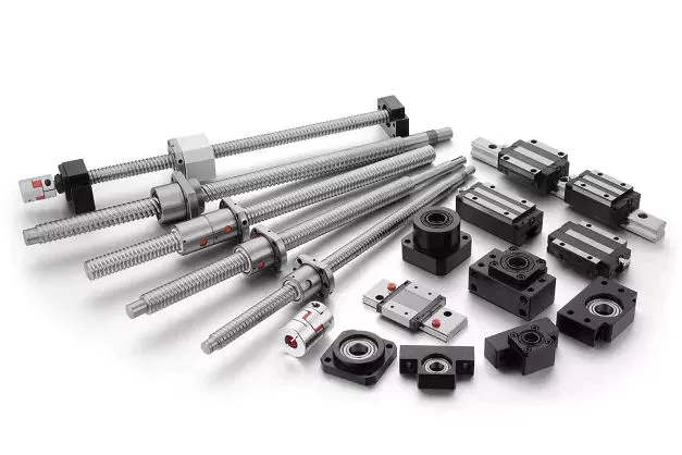
Typical applications

Ball screws are threaded shafts with a ball nut attached to them. These screws operate similar to ball bearings in which hardened steel balls travel a channel. Ball screws are usually used in linear-motion applications because of their high efficiency, load capacity, and positioning accuracy. Although these screws are similar in design to conventional lead screws, ball screws offer some distinct advantages. For example, ball screws are often used in machine tools, step photolithography machines, and microscopic integrated circuits.
For example, the use of larger balls reduces backlash in ball screws by reducing friction between the balls and the grooves. Ball screws can be preloaded using a spring or spacer between 2 ball nuts or a lead with a spherical offset. However, this method requires higher torque and can lead to excessive heat generation. It’s important to consider the size of preload before using a ball screw in a particular application.
Although the ball screws are highly durable, they are not without their disadvantages. For example, their metal-on-metal nature makes them louder than lead screw nuts. For these reasons, proper preloading is vital. Ball screws also have a very low friction coefficient. Ball screws are ideal for applications where backlash is of critical importance, such as wire bonding. A ball screw is the perfect solution for many applications that require precise motion.
Although ball screws are used in a wide variety of applications, they often are exposed to various types of contaminants. Dust, chips, and liquids can interfere with proper lubrication and shorten the lifespan of the ball screw assembly. Ultimately, these contaminants can lead to catastrophic failure of the assembly. They are also prone to abrasive wear and tear. To combat this, it’s important to lubricate your ball screws frequently.

Characteristics

The accuracy of a ball screw is 1 of its primary characteristics, so choosing the correct grade is critical. A ball screw with a C5 accuracy grade is typically used in machining centers, while a C3 or even a C1 screw might be needed for image processing or inspection equipment. Ball screw hardness is also an important consideration, as differences in the Ct and C grades will affect their accuracy. Ultimately, the higher the quality of the ball, the longer its life expectancy.
Numerous studies have been conducted to understand the mechanics of ball screw mechanisms. Cuttino et al. studied the nonlinear torque characteristics of ball screws. Then, by calculating the distribution of loads in all balls, they analyzed the load on the screw shaft and the ball screw.
CZPT has decades of experience in the design and production of ball screws for industrial use. With close to 50 years of know-how, this company is able to respond to a highly-complex market and develop new solutions. Their ball screw ranges range from basic to high-precision. Moreover, they can provide dedicated solutions for specific applications, ensuring the highest quality under all circumstances. And they can meet specific customer needs and requirements thanks to their extensive research and development.
A ball screw must be properly mounted. Improper mounting results in noise and vibration, accelerated wear, and material failure. Also, installed auxiliary components must be checked for faults. And, since ball screw mechanisms are often multi-stage, there are different types of ball screw mechanisms. There are 2 basic types: internal and external recirculation systems. There are many differences between the 2 types, but these 2 types have some fundamental similarities.
air-compressor

Maintenance

Ball screw maintenance can be done easily if you know the symptoms of a deteriorating ball screw. Several signs of deterioration can be detected during regular inspections: excessive vibrations, discoloration, and misalignment of the screw. If the screw is accompanied by excessive noises, there could be a bent screw shaft or misaligned bearing housings. Excessive buildup can also cause clicking noises. If you notice excessive noises from the screw, the return tube has probably been damaged or is broken. Other common symptoms include loss of positioning accuracy due to endplay in support bearings and excessive power consumption.
Another sign of a malfunctioning ball screw is noise, but if you can identify the problem before it occurs, you can flush it. A proper flush can solve any noise or extend the life of the ball screw assembly. Moreover, flushing the assembly can also reveal if the bearings are damaged or galled. If the bearings are broken, you can replace them with new ones. You can also contact a professional to perform PM for ball screw assembly.
A ball screw manufacturer recommends periodic lubrication to maximize uptime. In fact, ball screws are pre-lubricated at the factory, but periodic attention to lubrication is advisable. In addition, the lubrication reservoir must be designed to minimize the loss of lubricant. Finally, the wiper system must be designed to maximize wear protection. It is important to have a wiper system that is capable of sealing the nut and the screw shaft.
To choose a company for your ball screw maintenance, it is important to check their qualifications. The company must have a long-term track record in the servicing of different types of ball screws. Their customer service should include free evaluation. Additionally, the company should offer 3 services: reload, recondition, and replacement. Reload requires cleaning and polishing, reconditioning requires regrinding the ball nut, and replacement means replacing the screw with a new one. If you need a ball screw repair, it is best to contact a professional.

Repair options

A damaged ball screw can shut down a manufacturing line unless the component is repaired quickly. Fortunately, there are several options for repair, including rebuilding, reconditioning, and replacement. Reconditioning and replacement involve remanufacturing the ball screw and ball nut, but both options require new parts. Choosing the best option for your ball screw will depend on how much damage it has suffered and the amount of money it will cost.
In most cases, ball screw repairs can be done on rolled and ground screw types. The process involves eutectic spraying and grinding the screw back to size. Among the 3 repair options, level 4 repair is the most expensive, but it can bring back the lifespan of the screw. Depending on the severity of damage, AB Linear may recommend level 3 repair to repair damaged ball screws. The following process will restore the screw to good working condition.
First, inspect the ball screw for signs of damage. If the ball screw is making unusual noises or vibrations, replace any worn seals or wipers. Discoloration of the ball nut or lead can indicate an inadequate lubrication. Damaged lube lines can also be the cause of a ball screw failure. Repairing these issues is often a cheaper option than purchasing new. By choosing to repair the component instead of replacing it, you will be saving up to 70% of the cost of a replacement ball screw.
If you do experience problems with your ball screw, the best option is to repair it. The cost of replacing a ball screw is prohibitively high, and it can be difficult to find a qualified repair company that specializes in repairing ball screws. A qualified company can repair the ball screw for a small fee. Regardless of the type of screw, it’s always a good idea to seek qualified assistance if it is experiencing any of these problems.
air-compressor

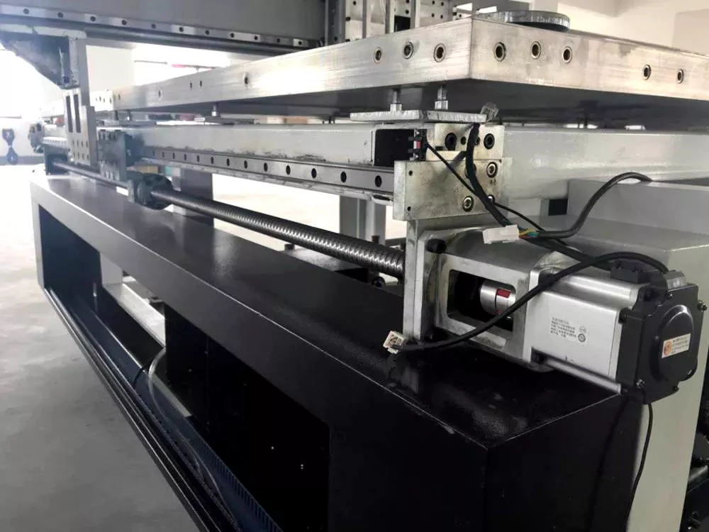
Application in steering systems

The conventional ball screw device is lacking a device to minimize noise and vibration. Both of these factors contribute to reduced performance and durability of a vehicle. The present invention overcomes these shortcomings. A ball screw device with a lower noise and vibration coefficient increases the durability and performance of a vehicle. In addition, it is easier to install and remove than the conventional version. Listed below are some advantages of ball screws in steering systems.
A ball screw is an important component of an automobile’s power steering system. This type of steering system requires a relatively low level of positional repeatability and precision. The screw is rotated by steering wheel motion and a ball nut engages with a Pitman arm. This arm is the primary linkage between the power steering box and the center link. By virtue of its low-cost and high-performance capabilities, ball screws are a desirable choice in many different automotive steering systems.
A ball screw device can be used in any electric power steering system. The shaft of the ball screw is threaded, and a ball nut is installed at its end. The screw includes a damper to reduce noise and vibration. The ball screw is often coupled with a power steering pump and electric motor to control the torque. In the present invention, the ball screw device incorporates a damper. This damper can increase the durability of the ball screw device.
As a leader in the manufacturing of ball screws, CZPT has been in the aerospace industry for decades. Its extensive experience and specialized expertise allows it to meet the diverse needs of the steering system market. Using this technology, CZPT offers a variety of solutions for this complex application. They can provide better positioning accuracy, higher durability and better control. So, if you’re in need of a ball screw in your steering system, contact CZPT today!

China manufacturer Customized High Quality High Strength Powder Metallurgy Transmission Gear Parts     near me factory China manufacturer Customized High Quality High Strength Powder Metallurgy Transmission Gear Parts     near me factory

China Good quality Gear Shift Lever (WG9925240020) CZPT Spare Parts for Hw19710 with Hot selling

Product Description

HangZhou CZPT Auto Parts specialize in
assembling,wholesale and distributing trucks spare parts.

We have more than 10 years experience in spare parts.

We deal in CZPT  Shacman CZPT CZPT  Beiben CZPT DFM etc heavy trucks spare parts.

Each product will undergo rigorous testing before shipment.

Professional Team

Our Advantages

1.Professional.

   We are professional. We can suuply the 100% exact information 
   according the Chassis No., assembley nameplate,Part NO., Picturers or Part Name.

2.Factory Price.

   We assemble and distributing spare parts. We have the most competitive prices.

3.One-stop service.
   We can supply HOWO CZPT CZPT CZPT Beiben CZPT DFM truck spare parts
   Cabin, engine, gearbox and chassis assembly and parts.

4.Service. We will send you every parts pictures to you for confirming.
   Picturess,Packages, quantity,weight and volume.

5.Packages:Wooden case,Pallet and carton.

6.Payment Terms:FOB HangZhou port (Any Chinese port),Door to door to your warehouse,CIP,CIFand EXW.

7.Payment Method:LC,TT and Wester Union and Installment.

Please contact us when you are free, looking forward to your inquiry.


Axle Spindle Types and Features

The axle spindle is an integral part of your vehicle’s suspension. There are several different types and features, including mounting methods, bearings, and functions. Read on for some basic information on axle spindles. The next part of the article will cover how to choose the correct axle spindle for your vehicle. This article will also discuss the different types of spindles available, including the differences between the rear and front bearings.
Driveshaft

Features

The improved axle spindle nut assembly is capable of providing additional performance benefits, including increased tire life and reduced seal failure. Its keyway features and radially inwardly extending teeth allow nut adjustment to be accomplished with precision. The invention further provides a unique, multi-piece locking mechanism that minimizes leakage and torque transfer. Its principles and features are detailed in the appended claims. For example, the improved axle spindle nut assembly is designed for use in vehicles that are equipped with a steering system.
The axle spindle nut assembly includes a nut 252 with threads 256 on its inner periphery. The axle spindle 50 also features threads 198 on its outer periphery. The nut is threaded onto the outboard end of the axle spindle 50 until it contacts the inboard surface of the axle spacer 26. In the assembled state, a bearing spacer 58 is also present on the axle spindle.
The axle spindle nut assembly can reduce axial end play between the wheel end assembly 52 and the axle spindle 50. It can be tightened to an extreme torque level, but if the thread faces separate, it will undercompress the bearing cone and spacer group. To minimize these disadvantages, the axle spindle nut assembly is a critical component of a wheel-end assembly. There are several types of axle spindle nuts.
The third embodiment of the axle spindle nut assembly 300 comprises an inner washer 202, an outer washer 310, and at least 1 screw 320. The axle spindle nut assembly 300 secures and preloads bearing cones 55, 57. Unlike the first embodiment, the axle spindle nut assembly 300 uses the inner washer 202, which is optional in the third embodiment. The inner washer 202 and outer washer 310 are similar to those of the first embodiment.

Functions

An axle spindle is 1 of the most important components of a vehicle’s suspension system. The spindle retains the position of bearings and a spacer in an axle by providing clamp force. The inner nut of an axle spindle should be properly torqued to ensure a secure fit. A spindle nut is also responsible for compressing bearings and spacers. If any of these components are missing, the spindle will not work properly.
An axle spindle is used in rear wheel drive cars. It carries the weight of the vehicle on the axle casing and transfers the torque from the differential to the wheels. The axle spindle and hub are secured on the spindle by large nuts. The axle spindle is a vital component of rear wheel drive vehicles. Hence, it is essential to understand the functions of axle spindle. These components are responsible for the smooth operation of a vehicle’s suspension system.
Axle spindles can be mounted in 3 ways: in the typical axle assembly, the spindles are bolted onto the ends of the tubular axle, and the axle is suspended by springs. Short stub-axle mounting uses a torsion beam that flexes to provide a smooth ride. A second washer is used to prevent excessive rotation of the axle spindle.
Apart from being a crucial component of the suspension system, the spindles of the wheels are responsible for guiding the vehicle in a straight line. They are connected to the steering axis and are used in different types of suspension systems. European cars use a MacPherson Strut suspension system in which the spindle is connected to the arms in the front and rear of the suspension frame. The MacPherson strut allows the shock absorber housing to turn the wheel.
Driveshaft

Methods of mounting

Various methods of mounting axle spindle are available. In general, these methods involve forming a tubular blank of uniform cross section and thickness, and receiving the bearing assembly against it. The spindle is then secured using a collar, which also serves as a bearing stop. In some cases, additional features are used to provide greater security. Some of these features may not be suitable for all applications. But they are generally suitable.
Axle spindle forming is usually done by progressive steps using hollow punches. The metallic body of the punch has an inner work surface, which receives the axle blank. A mandrel is fixed within the work opening of the punch. The punch body’s work surface forges the spindle about the mandrel. The punch has 2 ends, a closed and an open one.
A wheeled vehicle axle assembly (10) includes a cylindrical housing member (12 a) and a plurality of spindle mounting flanges (30) secured on the housing member. The spindles (16) are firmly attached to the housing member by means of coupling members. The coupling members are configured to distribute the bending loads imposed on the spindle by the axle. It is important to note that the coupling members can be either threaded or screwed.
Traditionally, axle spindles were made from tubular blanks of irregular thickness. This method allowed for a gradual reduction in diameter and eliminated the need for extra metal within the spindle. Similarly, axles made by cold forming eliminate the need for additional metal in the spindle. In this way, the overall cost of manufacture is also reduced. The material used for manufacturing axles also determines the size and shape of the final product.
Driveshaft

Bearings

A nut 16 is used to retain the wheel bearings on axle spindle 12. The nut comprises several parts. The first portion includes a plurality of threads and a deformable second portion. The nut may be disposed on the inboard or outboard end of the axle spindle. This type of nut is typically secured to the axle spindle by a retaining nut.
The bearings are installed in the spindle to allow the wheel hub to rotate. While bearings are greased, they can dry out over time. Consequently, you may hear a loud clicking sound when turning your vehicle. Alternatively, you may notice grease on the edges of your tires. Bearing failure can cause severe damage to your axle spindle. If you notice any of these symptoms, you may need to replace the bearings on your axle spindle. Fortunately, you can purchase the necessary bearing parts at O’Reilly Auto Parts.
There are 3 ways to mount an axle spindle. A typical axle assembly has the spindles bolted to the ends of the tubular axle. A torsion beam is also used to mount the spindles on the axle. This torsion beam acts like a spring to help make the ride smooth and bump-free. Lastly, the axle spindle is sometimes mounted as a bolt-on component.

Cost

If your axle spindle has been damaged, you may need to have it replaced. This part of the axle is relatively easy to replace, but you need to know how to do it correctly. To replace your axle spindle, you must first remove the damaged one. To do this, a technician will cut the weld. They will then thread the new 1 into the axle tube and torque it to specification. After that, they will weld the new axle spindle into place.
When you are thinking about the cost of an axle spindle replacement, you must first determine if it is worth it for your vehicle. It is generally a good idea to replace the spindle only if it is causing damage to your vehicle. You can also replace your axle housing if it is deteriorating. If you do not replace the spindle, you can risk damaging the axle housing. To save money, you can consider using a repair kit.
You can also purchase an axle nut socket set. Most wrenches have an adjusting socket for this purpose. The socket set should be suitable for most vehicle types. Axle spindle replacement costs around $500 to $600 before tax. However, you should be aware that these costs vary widely based on the type of vehicle you have. The parts can cost between $430 and $480, and the labor can cost anywhere from $50 to 70.

China Good quality Gear Shift Lever (WG9925240020) CZPT Spare Parts for Hw19710     with Hot sellingChina Good quality Gear Shift Lever (WG9925240020) CZPT Spare Parts for Hw19710     with Hot selling

China Custom Profiled Parts Customized Powder Metallurgy Engine Part Metal Gear Parts near me supplier

Product Description


Excellent powder metallurgy parts metallic sintered parts
We could offer various powder metallurgy parts including iron based and copper based with top quality and cheapest price, please only send the drawing or sample to us, we will according to customer’s requirement to make it. if you are interested in our product, please do not hesitate to contact us, we would like to offer the top quality and best service for you. thank you!

How do We Work with Our Clients
1. For a design expert or a big company with your own engineering team: we prefer to receive a fully RFQ pack from you including drawing, 3D model, quantity, pictures;

2. For a start-up company owner or green hand for engineering: just send an idea that you want to try, you don’t even need to know what casting is;

3. Our sales will reply you within 24 hours to confirm further details and give the estimated quote time;

4. Our engineering team will evaluate your inquiry and provide our offer within next 1~3 working days.

5. We can arrange a technical communication meeting with you and our engineers together anytime if required.

Place of origin: Jangsu,China
Type: Powder metallurgy sintering
Spare parts type: Powder metallurgy parts
Machinery Test report: Provided
Material: Iron,stainless,steel,copper
Key selling points: Quality assurance
Mould type: Tungsten steel
Material standard: MPIF 35,DIN 3571,JIS Z 2550
Application: Small home appliances,Lockset,Electric tool, automobile,
Brand Name: OEM SERVICE
Plating: Customized
After-sales Service: Online support
Processing: Powder Metallurgr,CNC Machining
Powder Metallurgr: High frequency quenching, oil immersion
Quality Control: 100% inspection

The Advantage of Powder Metallurgy Process

1. Cost effective
The final products can be compacted with powder metallurgy method ,and no need or can shorten the processing of machine .It can save material greatly and reduce the production cost .

2. Complex shapes
Powder metallurgy allows to obtain complex shapes directly from the compacting tooling ,without any machining operation ,like teeth ,splines ,profiles ,frontal geometries etc.

3. High precision
Achievable tolerances in the perpendicular direction of compacting are typically IT 8-9 as sintered,improvable up to IT 5-7 after sizing .Additional machining operations can improve the precision .

4. Self-lubrication
The interconnected porosity of the material can be filled with oils ,obtaining then a self-lubricating bearing :the oil provides constant lubrication between bearing and shaft ,and the system does not need any additional external lubricant .

5. Green technology
The manufacturing process of sintered components is certified as ecological ,because the material waste is very low ,the product is recyclable ,and the energy efficiency is good because the material is not molten. 

FAQ
Q1: What is the type of payment?
A: Usually you should prepay 50% of the total amount. The balance should be pay off before shipment.

Q2: How to guarantee the high quality?
A: 100% inspection. We have Carl Zeiss high-precision testing equipment and testing department to make sure every product of size,appearance and pressure test are good. 

Q3: How long will you give me the reply?
A: we will contact you in 12 hours as soon as we can.

Q4. How about your delivery time?
A: Generally, it will take 25 to 35 days after receiving your advance payment. The specific delivery time depends on the items and the quantity of your order. and if the item was non standard, we have to consider extra 10-15days for tooling/mould made.

Q5. Can you produce according to the samples or drawings?
A: Yes, we can produce by your samples or technical drawings. We can build the molds and fixtures.

Q6: How about tooling Charge?
A: Tooling charge only charge once when first order, all future orders would not charge again even tooling repair or under maintance.

Q7: What is your sample policy?
A: We can supply the sample if we have ready parts in stock, but the customers have to pay the sample cost and the courier cost.

Q8: How do you make our business long-term and good relationship?
A: 1. We keep good quality and competitive price to ensure our customers benefit ;
    2. We respect every customer as our friend and we sincerely do business and make friends with them, no matter where they come from.
 

How Metal Fabrication Benefits Agricultural Parts

agricultural parts

If you own an agricultural farm, you probably have a variety of different kinds of agricultural parts. These include tractors, hand tools, and other types of farm implements. Here, you’ll learn how to identify different parts and the importance of knowing what they do. Then, you can order them online to have them shipped directly to you. You can also contact different agricultural equipment dealers to find out where to buy agricultural parts. Regardless of where you get them, they’ll be worth the investment.
agriculturalparts

Metal fabricated agricultural parts

Regardless of the industry, metal fabricated agricultural parts can benefit a farm. For starters, metal fabricated parts are easier to replace than alternatives. Because metal is stronger than plastic, these parts can be made lighter. This means faster equipment movement and increased productivity. Metal can also be easily customized, allowing for a custom-made product. The benefits of metal fabrication extend far beyond the agricultural industry. Listed below are several of the benefits of using metal fabricated parts.
Agricultural equipment is exposed to harsh weather conditions. This is why it is imperative that metal fabricated agricultural parts are made with durable materials. Additionally, metal fabricated parts have a lower chance of corroding, which helps keep equipment running more efficiently. With such a long list of benefits, it’s easy to see why metal fabricated parts are so popular with farmers. And if your company needs agricultural equipment parts that can withstand the elements, you can depend on Hynes Industries.
Agricultural equipment requires metal parts that can withstand the rigorous workloads. As a trusted vendor, Evan’s Manufacturing provides comprehensive metal fabrication services for agricultural equipment. With our advanced laser cutting services, you can rest assured that your metal parts are in good hands. You’ll be able to make adjustments without affecting the integrity of the metal. And thanks to our streamlined process, the quality of your fabricated parts is unrivaled.
Whether you need a custom fitout for a new piece of farm equipment, or a new design for an existing piece, metal fabrication can help. Custom fitouts not only improve the comfort of the operator, but also increase the durability of your farm machinery. Almost every type of metal fabrication process is used in the agricultural industry. These include brazing, welding, soldering, drilling, milling, and laser engraving.
As the manufacturing process of agricultural machinery becomes increasingly automated, sheet metal fabrication has become an important part of the production process. This process allows for more precise and accurate processing of holes of various shapes and sizes, and the cost of production is lowered significantly. Additionally, because of its precision and stability, sheet metal fabrication is perfect for farming. Moreover, it’s easy to teach and maintain automated processes. With these machines, farmers can make small batches easily, improving the efficiency of agricultural production.
agriculturalparts

Agricultural machinery manufacturers

Agricultural machinery is a highly technological industry with a large market for OEM parts. The demand for agricultural equipment is expected to reach $118.2 billion by 2025, which is higher than the previous forecast. Today, modern tech developments have increased the productivity and profitability of farms, making it more profitable to use farm equipment. Moreover, the availability of OEM parts is a key driving factor for the market growth. The agricultural equipment market will see continued growth as manufacturers focus on safety, quality, and consistent improvement of their products.
AGCO Corporation is an agricultural machinery manufacturer based in Duluth, Georgia. It was formed through a merger with Allis-Chalmers in 1990. The company’s growth has been achieved through numerous acquisitions in farm machinery. It first acquired the Hesston forage and hay line from Fiat, which included a 50% share in a manufacturing joint venture with Case IH. Moreover, it acquired the White tractor business from Allied Products to expand its dealer network.
Among the major factors contributing to the supply chain breakdown for farm equipment manufacturers is the outbreak of COVID-19. The pandemic has affected the supply chain in several ways, including reducing the availability of raw materials and component parts. It also has affected the labor force by causing temporary layoffs and illness. Furthermore, the shortage of steel is causing manufacturers to struggle to meet demand. As a result, the company has to delay shipments to meet customer demand.
In addition to the above factors, the rising cost of labor is another factor driving equipment sales. Using auto-guidance systems to match the yield of a crop is an effective way to maximize yield while minimizing environmental impact. Another major factor driving agricultural equipment sales is the increasing cost of agricultural labor across regions. This pay differential between industrial workers and those in the agricultural sector is 1 of the most common secular drivers for demand for agricultural equipment.
A large proportion of agricultural equipment is oversized for economic reasons. For instance, a combine can do 3 different processes at once. It can also travel across several states or even countries. The need for reliable transportation companies is another critical factor in the industry. The majority of companies in this industry are family-owned and operated. A good transportation network is essential to keep equipment on the road. This is a major challenge for the industry.
The European Union accounts for a large proportion of agricultural machinery manufacturing, with total output of 28 billion euros (2014). The top 3 countries for production are Germany, Italy, and France, with each country accounting for around 17 per cent of the global total. The majority of leading international manufacturers maintain several production sites across the continent. The products produced at these facilities are typically for high-end customers. They can also be purchased from a variety of independent sources.
agriculturalparts

Agricultural equipment dealers

Agricultural equipment dealerships are facing a changing landscape. Today’s consumers expect businesses to be online 24/7, have faster response times, and allow them to make payments more conveniently. To keep up with these expectations, more dealers are making the switch to mobile apps. These apps simplify all areas of business, from sales to service, and allow technicians to receive work orders directly on their mobile devices. In addition, the growth of ag equipment manufacturers is fueling the trend of consolidation among ag equipment dealers.
Video marketing is especially useful for agricultural equipment dealers. Agricultural equipment dealers can utilize video marketing from firms such as Kirkpatrick Creative. Unlike text, video allows marketers to connect emotionally with their customers, by showing them a face. It is much more difficult to establish this connection through text, so video is a great way to reach potential customers. If a customer is satisfied with the process, they are more likely to buy from them again.
To succeed in sales of agricultural equipment, candidates should possess a combination of equipment knowledge, communication skills, and tenacity. Sales compensation packages for this industry are heavily based on commissions, so new salespeople should be prepared to work without a guaranteed monthly check. Agricultural equipment dealers should be ready for this kind of change in the coming years and prepare their sales funnels to make the transition. In addition, they should make sure that their phone numbers are prominently displayed.
The laws governing agricultural equipment dealers vary from state to state. These laws protect farm equipment dealers by outlining their rights as a supplier and a manufacturer. While these laws may have some commonalities, they do have some differences, which makes them essential to fully understand. Several procedures which are legal in 1 state may not be allowed in another. For this reason, it is vital that the dealer understand the laws of his state and be familiar with the relevant legislation.
The shortage of labor in the agriculture sector is a major challenge for many growers. But the shortage of labor could spur sales of robotics and automation equipment that simplify the farming process. With the right tools, a farm can run more efficiently and reduce its worker headcount. Therefore, the lack of labor will continue to be a major problem for agricultural equipment dealers. With this in mind, it is imperative to choose the right dealer for the job.
The influx of new equipment has made it difficult for agricultural equipment manufacturers to meet demand. Many companies have struggled to get implements to dealerships on time, making the overall situation even more complicated. Agricultural equipment dealers have to wait weeks or even months for their new machines to be delivered to farmers. A tractor from John Deere, for instance, can take 5 or 6 weeks to arrive in a dealership. It can now take 18 to 22 weeks, depending on the size of the order.

China Custom Profiled Parts Customized Powder Metallurgy Engine Part Metal Gear Parts     near me supplier China Custom Profiled Parts Customized Powder Metallurgy Engine Part Metal Gear Parts     near me supplier

China Standard Custom CNC Machining Parts CNC Steel Gear CNC Machining Parts with Free Design Custom

Product Description

custom cnc machining parts cnc steel gear cnc machining parts

Product name oem cnc machining parts aluminum wallmount brackets
Material aluminum alloy 6061,6063,stainless steel ,cooper,adc12,a380,and others
Drawing file .pdf.stp.igs .
Mold led time  25-30days,according to quantity and design drawings
Sample we offer free samples.
Certificates TUV
MOQ Low moq,1 pcs for sample checking is available 
Other Equipments vibration grinding machines,shot blasting machines
Service offer assembly if customer’s need

FAQ
Q1. Can I have a sample order for Die casting product?
A: Yes, we welcome sample order to test and check quality. Mixed samples are acceptable.

Q2. What about the lead time?
A:Sample needs 3-5 days, mass production time needs 1-2 weeks for order quantity more than.

Q3. Do you have any MOQ limit for Die casting product order?
A: Low MOQ, 1pc for sample checking is available.
 
Q4. How do you ship the goods and how long does it take to arrive?
A: We usually ship by DHL, UPS, FedEx or TNT. It usually takes 3-5 days to arrive. Airline and sea shipping also optional.

Q5. How to proceed an order for Die casting product?
A: Firstly let us know your requirements or application. Secondly We quote according to your requirements or our suggestions. Thirdly customer confirms the samples and places deposit for formal order. Fourthly We arrange the production.
 
Q6. Is it OK to print my logo on Die casting product?
A: Yes. Please inform us formally before our production and confirm the design firstly based on our sample.

Q7: Do you offer guarantee for the products?
A: Yes, we offer 2-5 years warranty to our products.
 
Q8: How to deal with the faulty?
A: Firstly, Our products are produced in strict quality control system and the defective rate will be less than 0.2%. Secondly, during the guarantee period, we will send new lights with new order for small quantity. For defective batch products, we will repair them and resend them to you or we can discuss the solution i ncluding re-call according to real situation.

The 5 components of an axle, their function and installation

If you’re considering replacing an axle in your vehicle, you should first understand what it is. It is the component that transmits electricity from 1 part to another. Unlike a fixed steering wheel, the axles are movable. The following article will discuss the 5 components of the half shaft, their function and installation. Hopefully you were able to identify the correct axle for your vehicle. Here are some common problems you may encounter along the way.
Driveshaft

five components

The 5 components of the shaft are flange, bearing surface, spline teeth, spline pitch and pressure angle. The higher the number of splines, the stronger the shaft. The maximum stress that the shaft can withstand increases with the number of spline teeth and spline pitch. The diameter of the shaft times the cube of the pressure angle and spline pitch determines the maximum stress the shaft can withstand. For extreme load applications, use axles made from SAE 4340 and SAE 1550 materials. In addition to these 2 criteria, spline rolling produces a finer grain structure in the material. Cutting the splines reduces the strength of the shaft by 30% and increases stress.
The asymmetric length of the shaft implies different torsional stiffness. A longer shaft, usually the driver’s side, can handle more twist angles before breaking. When the long axis is intact, the short axis usually fails, but this does not always happen. Some vehicles have short axles that permanently break, causing the same failure rate for both. It would be ideal if both shafts were the same length, they would share the same load.
In addition to the spline pitch, the diameter of the shaft spline is another important factor. The small diameter of a spline is the radius at which it resists twisting. Therefore, the splines must be able to absorb shock loads and shocks while returning to their original shape. To achieve these goals, the spline pitch should be 30 teeth or less, which is standard on Chrysler 8.75-inch and GM 12-bolt axles. However, a Ford 8.8-inch axle may have 28 or 31 tooth splines.
In addition to the CV joints, the axles also include CV joints, which are located on each end of the axle. ACV joints, also known as CV joints, use a special type of bearing called a pinion. This is a nut that meshes with the side gear to ensure proper shaft alignment. If you notice a discrepancy, take your car to a shop and have it repaired immediately.

Function

Axles play several important roles in a vehicle. It transfers power from the transmission to the rear differential gearbox and the wheels. The shaft is usually made of steel with cardan joints at both ends. Shaft Shafts can be stationary or rotating. They are all creatures that can transmit electricity and loads. Here are some of their functions. Read on to learn more about axles. Some of their most important features are listed below.
The rear axle supports the weight of the vehicle and is connected to the front axle through the axle. The rear axle is suspended from the body, frame and axle housing, usually spring loaded, to cushion the vehicle. The driveshaft, also called the propshaft, is located between the rear wheels and the differential. It transfers power from the differential to the drive wheels.
The shaft is made of mild steel or alloy steel. The latter is stronger, more corrosion-resistant and suitable for special environments. Forged for large diameter shafts. The cross section of the shaft is circular. While they don’t transmit torque, they do transmit bending moment. This allows the drive train to rotate. If you’re looking for new axles, it’s worth learning more about how they work.
The shaft consists of 3 distinct parts: the main shaft and the hub. The front axle assembly has a main shaft, while the rear axle is fully floating. Axles are usually made of chrome molybdenum steel. The alloy’s chromium content helps the axle maintain its tensile strength even under extreme conditions. These parts are welded into the axle housing.
Driveshaft

Material

The material used to make the axle depends on the purpose of the vehicle. For example, overload shafts are usually made of SAE 4340 or 1550 steel. These steels are high strength low alloy alloys that are resistant to bending and buckling. Chromium alloys, for example, are made from steel and have chromium and molybdenum added to increase their toughness and durability.
The major diameter of the shaft is measured at the tip of the spline teeth, while the minor diameter is measured at the bottom of the groove between the teeth. These 2 diameters must match, otherwise the half shaft will not work properly. It is important to understand that the brittleness of the material should not exceed what is required to withstand normal torque and twisting, otherwise it will become unstable. The material used to make the axles should be strong enough to carry the weight of a heavy truck, but must also be able to withstand torque while still being malleable.
Typically, the shaft is case hardened using an induction process. Heat is applied to the surface of the steel to form martensite and austenite. The shell-core interface transitions from compression to tension, and the peak stress level depends on the process variables used, including heating time, residence time, and hardenability of the steel. Some common materials used for axles are listed below. If you’re not sure which material is best for your axle, consider the following guide.
The axle is the main component of the axle and transmits the transmission motion to the wheels. In addition, they regulate the drive between the rear hub and the differential sun gear. The axle is supported by axle bearings and guided to the path the wheels need to follow. Therefore, they require proper materials, processing techniques and thorough inspection methods to ensure lasting performance. You can start by selecting the material for the shaft.
Choosing the right alloy for the axle is critical. You will want to find an alloy with a low carbon content so it can harden to the desired level. This is an important consideration because the hardenability of the alloy is important to the durability and fatigue life of the axle. By choosing the right alloy, you will be able to minimize these problems and improve the performance of your axle. If you have no other choice, you can always choose an alloy with a higher carbon content, but it will cost you more money.
Driveshaft

Install

The process of installing a new shaft is simple. Just loosen the axle nut and remove the set bolt. You may need to tap a few times to get a good seal. After installation, check the shaft at the points marked “A” and “D” to make sure it is in the correct position. Then, press the “F” points on the shaft flange until the points are within 0.002″ of the runout.
Before attempting to install the shaft, check the bearings to make sure they are aligned. Some bearings may have backlash. To determine the amount of differential clearance, use a screwdriver or clamp lever to check. Unless it’s caused by a loose differential case hub, there shouldn’t be any play in the axle bearings. You may need to replace the differential case if the axles are not mounted tightly. Thread adjusters are an option for adjusting drive gear runout. Make sure the dial indicator is mounted on the lead stud and loaded so that the plunger is at right angles to the drive gear.
To install the axle, lift the vehicle with a jack or crane. The safety bracket should be installed under the frame rails. If the vehicle is on a jack, the rear axle should be in the rebound position to ensure working clearance. Label the drive shaft assemblies and reinstall them in their original positions. Once everything is back in place, use a 2-jaw puller to pry the yoke and flange off the shaft.
If you’ve never installed a half shaft before, be sure to read these simple steps to get it right. First, check the bearing surfaces to make sure they are clean and undamaged. Replace them if they look battered or dented. Next, remove the seal attached to the bushing hole. Make sure the shaft is installed correctly and the bearing surfaces are level. After completing the installation process, you may need to replace the bearing seals.

China Standard Custom CNC Machining Parts CNC Steel Gear CNC Machining Parts     with Free Design CustomChina Standard Custom CNC Machining Parts CNC Steel Gear CNC Machining Parts     with Free Design Custom

China Best Sales Gear Bevel 11t 32781-13200 CZPT Tractor Parts L4708 Made in Japan with Good quality

Product Description

Kubota Tractor parts

RELATED PRODUCTS

KUBOTA TRACTOR PARTS :M6040,M7040,M9540,L3408,L4508,L3608,L4708

KUBOTA HARVESTER PARTS:PRO688,PRO758,PRO988,DC60,DC68G,DC70,
                                                    DC70PLUS,DC95,DC105

KUBOTA ENGINE PARTS:V2203,V2403,V2603,V3000,V3600,V3800,D1105,D782,D1803

KUBOTA  RICE TRANSPLANTER PARTS:SVP-6CMD,SPV-8CMD,NSPU-68CMD

PACKAING AND SHIPPING

OUR SERVICES

Product: We can provide high quality products with competitive price.

Production Capacity: we have good production capacity and we have enough spare parts stock and
can start to pack at once when you confirm your order.

Online Service: We will reply you at once when we get your enquiry, 24hours online service for you.
Welcome to contact us by email, ,viber,IMO

COMPANY INFORMATION 

Our Company is a professional agricultural machinery spare parts Manufacturer in China,
We specializes in agricultural machinery and accessories, we have a wealth of experience
in parts development, processing, production, so we are well aware of market demand and
can provide good products for our customers.We have been export to many countries such
as Southeast Asia, Australia, American, South America and Africa. We have enough parts
stock and can send out goods soon when customer place order. Dear Friends, it is our
pleasure to know you and look forward to your cooperation.We have a warehouse of 5000 square meters.


How to Identify a Faulty Drive Shaft

The most common problems associated with automotive driveshafts include clicking and rubbing noises. While driving, the noise from the driver’s seat is often noticeable. An experienced auto mechanic can easily identify whether the sound is coming from both sides or from 1 side. If you notice any of these signs, it’s time to send your car in for a proper diagnosis. Here’s a guide to determining if your car’s driveshaft is faulty:
air-compressor

Symptoms of Driveshaft Failure

If you’re having trouble turning your car, it’s time to check your vehicle’s driveshaft. A bad driveshaft can limit the overall control of your car, and you should fix it as soon as possible to avoid further problems. Other symptoms of a propshaft failure include strange noises from under the vehicle and difficulty shifting gears. Squeaking from under the vehicle is another sign of a faulty driveshaft.
If your driveshaft fails, your car will stop. Although the engine will still run, the wheels will not turn. You may hear strange noises from under the vehicle, but this is a rare symptom of a propshaft failure. However, you will have plenty of time to fix the problem. If you don’t hear any noise, the problem is not affecting your vehicle’s ability to move.
The most obvious signs of a driveshaft failure are dull sounds, squeaks or vibrations. If the drive shaft is unbalanced, it is likely to damage the transmission. It will require a trailer to remove it from your vehicle. Apart from that, it can also affect your car’s performance and require repairs. So if you hear these signs in your car, be sure to have it checked by a mechanic right away.

Drive shaft assembly

When designing a propshaft, the design should be based on the torque required to drive the vehicle. When this torque is too high, it can cause irreversible failure of the drive shaft. Therefore, a good drive shaft design should have a long service life. Here are some tips to help you design a good driveshaft. Some of the main components of the driveshaft are listed below.
Snap Ring: The snap ring is a removable part that secures the bearing cup assembly in the yoke cross hole. It also has a groove for locating the snap ring. Spline: A spline is a patented tubular machined element with a series of ridges that fit into the grooves of the mating piece. The bearing cup assembly consists of a shaft and end fittings.
U-joint: U-joint is required due to the angular displacement between the T-shaped housing and the pinion. This angle is especially large in raised 4x4s. The design of the U-joint must guarantee a constant rotational speed. Proper driveshaft design must account for the difference in angular velocity between the shafts. The T-bracket and output shaft are attached to the bearing caps at both ends.
air-compressor

U-joint

Your vehicle has a set of U-joints on the driveshaft. If your vehicle needs to be replaced, you can do it yourself. You will need a hammer, ratchet and socket. In order to remove the U-joint, you must first remove the bearing cup. In some cases you will need to use a hammer to remove the bearing cup, you should be careful as you don’t want to damage the drive shaft. If you cannot remove the bearing cup, you can also use a vise to press it out.
There are 2 types of U-joints. One is held by a yoke and the other is held by a c-clamp. A full ring is safer and ideal for vehicles that are often used off-road. In some cases, a full circle can be used to repair a c-clamp u-joint.
In addition to excessive torque, extreme loads and improper lubrication are common causes of U-joint failure. The U-joint on the driveshaft can also be damaged if the engine is modified. If you are driving a vehicle with a heavily modified engine, it is not enough to replace the OE U-joint. In this case, it is important to take the time to properly lubricate these components as needed to keep them functional.

tube yoke

QU40866 Tube Yoke is a common replacement for damaged or damaged driveshaft tubes. They are desirably made of a metallic material, such as an aluminum alloy, and include a hollow portion with a lug structure at 1 end. Tube yokes can be manufactured using a variety of methods, including casting and forging. A common method involves drawing solid elements and machining them into the final shape. The resulting components are less expensive to produce, especially when compared to other forms.
The tube fork has a connection point to the driveshaft tube. The lug structure provides attachment points for the gimbal. Typically, the driveshaft tube is 5 inches in diameter and the lug structure is 4 inches in diameter. The lug structure also serves as a mounting point for the drive shaft. Once installed, Tube Yoke is easy to maintain. There are 2 types of lug structures: 1 is forged tube yoke and the other is welded.
Heavy-duty series drive shafts use bearing plates to secure the yoke to the U-joint. All other dimensions are secured with external snap rings. Yokes are usually machined to accept U-bolts. For some applications, grease fittings are used. This attachment is more suitable for off-road vehicles and performance vehicles.
air-compressor

end yoke

The end yoke of the drive shaft is an integral part of the drive train. Choosing a high-quality end yoke will help ensure long-term operation and prevent premature failure. Pat’s Driveline offers a complete line of automotive end yokes for power take-offs, differentials and auxiliary equipment. They can also measure your existing parts and provide you with high quality replacements.
A U-bolt is an industrial fastener with threaded legs. When used on a driveshaft, it provides greater stability in unstable terrain. You can purchase a U-bolt kit to secure the pinion carrier to the drive shaft. U-bolts also come with lock washers and nuts. Performance cars and off-road vehicles often use this type of attachment. But before you install it, you have to make sure the yoke is machined to accept it.
End yokes can be made of aluminum or steel and are designed to provide strength. It also offers special bolt styles for various applications. CZPT’s drivetrain is also stocked with a full line of automotive flange yokes. The company also produces custom flanged yokes for many popular brands. Since the company has a comprehensive line of replacement flange yokes, it can help you transform your drivetrain from non-serviceable to serviceable.

bushing

The first step in repairing or replacing an automotive driveshaft is to replace worn or damaged bushings. These bushings are located inside the drive shaft to provide a smooth, safe ride. The shaft rotates in a rubber sleeve. If a bushing needs to be replaced, you should first check the manual for recommendations. Some of these components may also need to be replaced, such as the clutch or swingarm.

China Best Sales Gear Bevel 11t 32781-13200 CZPT Tractor Parts L4708 Made in Japan     with Good qualityChina Best Sales Gear Bevel 11t 32781-13200 CZPT Tractor Parts L4708 Made in Japan     with Good quality

China factory OEM Manufacturer Drive Gear Shaft CNC Machining Parts for Industrial General Use near me factory

Product Description

Non-standard custom-made gear, please contact us to customize your exclusive gear!
 

Item Description
Product
Name
OEM Manufacturer Drive Gear Shaft CNC Machining Parts For Industrial General Use

Material
Available


Stainless Steel SS201, SS303, SS304, SS316, 17-4PH, etc.
Steel 20#, 45#, 40Cr, Q235, etc.
Brass C36000(C26800), C37700(HPb59), C38500(HP6 58), C27200(CuzN37), etc.
Bronze C51000, C52100, C54400, etc.
Aluminum Al6061, Al6063, Al7075, Al5052, etc.
Iron 1213, 12L14, 1215, etc.
Plastic ABS, PC, POM, Nylon, PTFE, PP, etc.
Others like fiberglass also can be machined. We handle many other type of materials, please contact us for further discussion.
Surface Treatment Zinc/Chrome/Nickel/Sliver/Gold Plating, Powder Coating, Sand Blasting, Galvanized, Anodized, Heat Treatment, Laser Marking, Polished, etc.
Machining Process CNC Milling and Turning, Drilling, Grinding, Bending, Stamping, Tapping, Laser Machining, etc.
Size of CNC Machining 1~2400mm, depend on the product and customers requirements
Tolerance of Machining Parts ±0.1~±0.002mm, depend on the product and customers requirements
Detecting Instrument Calipers, Micro Calipers, Caliper Gauge, CMM, Pass Meter, etc.
DWG
Format
PDF, DWG, IGES, STP, SolidWorks, etc
Packing
Method
Standard PE Bag + Carton + Pallet, or pack on customer’ s request in perfect condition.
Application  Equipment/Machinery, Medical & Technological parts, The Automotive/motorcycle parts, The optacal instrument parts, The power tool parts, Bicycle parts, The agricultural parts, The sensor metal parts, The optacal fiber parts, The CNC punching metal parts
Others We accept small order even 1pc, please contact us directly for further discussion!

1. Provide large-scale laser cutting machine, non-metal cutting machine, CNC(engraving and milling machine,
computer center), CNC lathe, ordinary lathe, milling lathe, wire cutting machine, CNC bending machine, etc.

2. Fast proofing with fastest one-day sample.

3. Metal materials and non-metal materials all are accepted to process.

4. We are a one-stop machining factory, from setting mould, casting to various processing and assembly.

5. Non-standard machining!
    One piece order is accepted, welcome to send us your inquiry!


Equipments Lists:

Milling Machine CNC Computer Center
 
CNC Lathe Ordinary Lathe CNC Lathe
CNC Bending Machine
 
Drilling Machine Laser-beam Welding Machine Laser Cutting Machine CNC Turning Machine


Worm Shafts and Gearboxes

If you have a gearbox, you may be wondering what the best Worm Shaft is for your application. There are several things to consider, including the Concave shape, Number of threads, and Lubrication. This article will explain each factor and help you choose the right Worm Shaft for your gearbox. There are many options available on the market, so don’t hesitate to shop around. If you are new to the world of gearboxes, read on to learn more about this popular type of gearbox.
worm shaft

Concave shape

The geometry of a worm gear varies considerably depending on its manufacturer and its intended use. Early worms had a basic profile that resembled a screw thread and could be chased on a lathe. Later, tools with a straight sided g-angle were developed to produce threads that were parallel to the worm’s axis. Grinding was also developed to improve the finish of worm threads and minimize distortions that occur with hardening.
To select a worm with the proper geometry, the diameter of the worm gear must be in the same unit as the worm’s shaft. Once the basic profile of the worm gear is determined, the worm gear teeth can be specified. The calculation also involves an angle for the worm shaft to prevent it from overheating. The angle of the worm shaft should be as close to the vertical axis as possible.
Double-enveloping worm gears, on the other hand, do not have a throat around the worm. They are helical gears with a straight worm shaft. Since the teeth of the worm are in contact with each other, they produce significant friction. Unlike double-enveloping worm gears, non-throated worm gears are more compact and can handle smaller loads. They are also easy to manufacture.
The worm gears of different manufacturers offer many advantages. For instance, worm gears are 1 of the most efficient ways to increase torque, while lower-quality materials like bronze are difficult to lubricate. Worm gears also have a low failure rate because they allow for considerable leeway in the design process. Despite the differences between the 2 standards, the overall performance of a worm gear system is the same.
The cone-shaped worm is another type. This is a technological scheme that combines a straight worm shaft with a concave arc. The concave arc is also a useful utility model. Worms with this shape have more than 3 contacts at the same time, which means they can reduce a large diameter without excessive wear. It is also a relatively low-cost model.
worm shaft

Thread pattern

A good worm gear requires a perfect thread pattern. There are a few key parameters that determine how good a thread pattern is. Firstly, the threading pattern must be ACME-threaded. If this is not possible, the thread must be made with straight sides. Then, the linear pitch of the “worm” must be the same as the circular pitch of the corresponding worm wheel. In simple terms, this means the pitch of the “worm” is the same as the circular pitch of the worm wheel. A quick-change gearbox is usually used with this type of worm gear. Alternatively, lead-screw change gears are used instead of a quick-change gear box. The pitch of a worm gear equals the helix angle of a screw.
A worm gear’s axial pitch must match the circular pitch of a gear with a higher axial pitch. The circular pitch is the distance between the points of teeth on the worm, while the axial pitch is the distance between the worm’s teeth. Another factor is the worm’s lead angle. The angle between the pitch cylinder and worm shaft is called its lead angle, and the higher the lead angle, the greater the efficiency of a gear.
Worm gear tooth geometry varies depending on the manufacturer and intended use. In early worms, threading resembled the thread on a screw, and was easily chased using a lathe. Later, grinding improved worm thread finishes and minimized distortions from hardening. As a result, today, most worm gears have a thread pattern corresponding to their size. When selecting a worm gear, make sure to check for the number of threads before purchasing it.
A worm gear’s threading is crucial in its operation. Worm teeth are typically cylindrical, and are arranged in a pattern similar to screw or nut threads. Worm teeth are often formed on an axis of perpendicular compared to their parallel counterparts. Because of this, they have greater torque than their spur gear counterparts. Moreover, the gearing has a low output speed and high torque.

Number of threads

Different types of worm gears use different numbers of threads on their planetary gears. A single threaded worm gear should not be used with a double-threaded worm. A single-threaded worm gear should be used with a single-threaded worm. Single-threaded worms are more effective for speed reduction than double-threaded ones.
The number of threads on a worm’s shaft is a ratio that compares the pitch diameter and number of teeth. In general, worms have 1,2,4 threads, but some have three, five, or six. Counting thread starts can help you determine the number of threads on a worm. A single-threaded worm has fewer threads than a multiple-threaded worm, but a multi-threaded worm will have more threads than a mono-threaded planetary gear.
To measure the number of threads on a worm shaft, a small fixture with 2 ground faces is used. The worm must be removed from its housing so that the finished thread area can be inspected. After identifying the number of threads, simple measurements of the worm’s outside diameter and thread depth are taken. Once the worm has been accounted for, a cast of the tooth space is made using epoxy material. The casting is moulded between the 2 tooth flanks. The V-block fixture rests against the outside diameter of the worm.
The circular pitch of a worm and its axial pitch must match the circular pitch of a larger gear. The axial pitch of a worm is the distance between the points of the teeth on a worm’s pitch diameter. The lead of a thread is the distance a thread travels in 1 revolution. The lead angle is the tangent to the helix of a thread on a cylinder.
The worm gear’s speed transmission ratio is based on the number of threads. A worm gear with a high ratio can be easily reduced in 1 step by using a set of worm gears. However, a multi-thread worm will have more than 2 threads. The worm gear is also more efficient than single-threaded gears. And a worm gear with a high ratio will allow the motor to be used in a variety of applications.
worm shaft

Lubrication

The lubrication of a worm gear is particularly challenging, due to its friction and high sliding contact force. Fortunately, there are several options for lubricants, such as compounded oils. Compounded oils are mineral-based lubricants formulated with 10 percent or more fatty acid, rust and oxidation inhibitors, and other additives. This combination results in improved lubricity, reduced friction, and lower sliding wear.
When choosing a lubricant for a worm shaft, make sure the product’s viscosity is right for the type of gearing used. A low viscosity will make the gearbox difficult to actuate and rotate. Worm gears also undergo a greater sliding motion than rolling motion, so grease must be able to migrate evenly throughout the gearbox. Repeated sliding motions will push the grease away from the contact zone.
Another consideration is the backlash of the gears. Worm gears have high gear ratios, sometimes 300:1. This is important for power applications, but is at the same time inefficient. Worm gears can generate heat during the sliding motion, so a high-quality lubricant is essential. This type of lubricant will reduce heat and ensure optimal performance. The following tips will help you choose the right lubricant for your worm gear.
In low-speed applications, a grease lubricant may be sufficient. In higher-speed applications, it’s best to apply a synthetic lubricant to prevent premature failure and tooth wear. In both cases, lubricant choice depends on the tangential and rotational speed. It is important to follow manufacturer’s guidelines regarding the choice of lubricant. But remember that lubricant choice is not an easy task.

China factory OEM Manufacturer Drive Gear Shaft CNC Machining Parts for Industrial General Use     near me factory China factory OEM Manufacturer Drive Gear Shaft CNC Machining Parts for Industrial General Use     near me factory

China Hot selling OEM Sinted Steel Pinion Gear Spur Gear Small Gear Parts with Free Design Custom

Product Description

We offer OEM metal parts & accessories for  electornic appliances , mechanical device machine parts through metal injection molding process , powder injection molding. 
The Metal Injection Molding process is characterized by high pressure injection of powdered metals and binders rather than the conventional gravity fed processes.
The main applications for this technique are to produce small and often more complex parts often ranging in weight from 0.5 to 150g.

Step 1:  Feedstock 

  • Very fine metal powders are combined with thermoplastic and wax binders in a precise recipe. A proprietary compounding process creates a homogenous pelletized feedstock that can be injection molded just like plastic. This achieves ultra-high density and close tolerances over high-production runs. 

  • Unlike standard powder metallurgy, which can achieve only 80-90% of theoretical density, MIM results in 95-100%. This means we can achieve close tolerances and reduce costs by producing small, complex parts over high production runs.

Step 2: Molding

  • The feedstock is heated and injected into a mold cavity under high pressure. This enables us to produce extremely complex shapes and allows for shorter cycle times.
  • Once molded, the component is referred to as a “green” part. Its geometry is identical to the finished piece but is about 20% larger to allow for shrinkage during the final sintering phase.

Step 3: Debinding

  • Binder removal (debinding) involves a controlled process to remove most of the binders and prepare the part for the final step – sintering.
  • Once debinding is complete, the component is referred to as “brown.”

Step 4: Sintering 

  • The brown part is held together by a small amount of the binder, and is very fragile.
  • Sintering eliminates the remaining binder and gives the part its final geometry and strength.
  • During sintering, the part is subjected to temperatures near the melting point of the material.

The advantages of  Powder metallurgy, metal injection molding for metal fabrications :

  • No limits for designers
  • Merge 2 or more parts into one
  • MIM can reduce cost of assemblies
  • Green part and post-processing for special requirements

These and other clients operate within an array of industry sectors including:

  • Medical
  • Aerospace
  • Automotive
  • Industrial
  • Telecommunications
  • Gas Analysis
  • Agricultural

Customized metal parts specification


Product type custom made sintered steel parts , precision components, cnc machinery processing parts ,metal injection molding MIM parts ,Titanium parts ,custom stainless steel parts , Sintered spare parts ,tungsten alloy parts
Material Aluminum(6061,6063,7075…), Stainless Steel(301,302,303,304…), Brass, Copper, metal sheetl
Process Metal injection molding , powder metallurgy ,cnc machining
Treatment  Powder Costing,Chroming,Electropolishing ,Blackening
Galvanized,Painting,Anodizing,Laser Cutting,Texture, Sanblasting,Polishing , Silk Screening 
Tolerance ±0.3%
Drawing format DWG ,IGS , STP
Delivery time  20 days for mass production

Welcome OEM /ODM metal injection molding MIM customized gears fabrication.

Custom metal parts

Workshop

An Overview of Worm Shafts and Gears

This article provides an overview of worm shafts and gears, including the type of toothing and deflection they experience. Other topics covered include the use of aluminum versus bronze worm shafts, calculating worm shaft deflection and lubrication. A thorough understanding of these issues will help you to design better gearboxes and other worm gear mechanisms. For further information, please visit the related websites. We also hope that you will find this article informative.
worm shaft

Double throat worm gears

The pitch diameter of a worm and the pitch of its worm wheel must be equal. The 2 types of worm gears have the same pitch diameter, but the difference lies in their axial and circular pitches. The pitch diameter is the distance between the worm’s teeth along its axis and the pitch diameter of the larger gear. Worms are made with left-handed or right-handed threads. The lead of the worm is the distance a point on the thread travels during 1 revolution of the worm gear. The backlash measurement should be made in a few different places on the gear wheel, as a large amount of backlash implies tooth spacing.
A double-throat worm gear is designed for high-load applications. It provides the tightest connection between worm and gear. It is crucial to mount a worm gear assembly correctly. The keyway design requires several points of contact, which block shaft rotation and help transfer torque to the gear. After determining the location of the keyway, a hole is drilled into the hub, which is then screwed into the gear.
The dual-threaded design of worm gears allows them to withstand heavy loads without slipping or tearing out of the worm. A double-throat worm gear provides the tightest connection between worm and gear, and is therefore ideal for hoisting applications. The self-locking nature of the worm gear is another advantage. If the worm gears are designed well, they are excellent for reducing speeds, as they are self-locking.
When choosing a worm, the number of threads that a worm has is critical. Thread starts determine the reduction ratio of a pair, so the higher the threads, the greater the ratio. The same is true for the worm helix angles, which can be one, two, or 3 threads long. This varies between a single thread and a double-throat worm gear, and it is crucial to consider the helix angle when selecting a worm.
Double-throat worm gears differ in their profile from the actual gear. Double-throat worm gears are especially useful in applications where noise is an issue. In addition to their low noise, worm gears can absorb shock loads. A double-throat worm gear is also a popular choice for many different types of applications. These gears are also commonly used for hoisting equipment. Its tooth profile is different from that of the actual gear.
worm shaft

Bronze or aluminum worm shafts

When selecting a worm, a few things should be kept in mind. The material of the shaft should be either bronze or aluminum. The worm itself is the primary component, but there are also addendum gears that are available. The total number of teeth on both the worm and the addendum gear should be greater than 40. The axial pitch of the worm needs to match the circular pitch of the larger gear.
The most common material used for worm gears is bronze because of its desirable mechanical properties. Bronze is a broad term referring to various copper alloys, including copper-nickel and copper-aluminum. Bronze is most commonly created by alloying copper with tin and aluminum. In some cases, this combination creates brass, which is a similar metal to bronze. The latter is less expensive and suitable for light loads.
There are many benefits to bronze worm gears. They are strong and durable, and they offer excellent wear-resistance. In contrast to steel worms, bronze worm gears are quieter than their counterparts. They also require no lubrication and are corrosion-resistant. Bronze worms are popular with small, light-weight machines, as they are easy to maintain. You can read more about worm gears in CZPT’s CZPT.
Although bronze or aluminum worm shafts are the most common, both materials are equally suitable for a variety of applications. A bronze shaft is often called bronze but may actually be brass. Historically, worm gears were made of SAE 65 gear bronze. However, newer materials have been introduced. SAE 65 gear bronze (UNS C90700) remains the preferred material. For high-volume applications, the material savings can be considerable.
Both types of worms are essentially the same in size and shape, but the lead on the left and right tooth surfaces can vary. This allows for precise adjustment of the backlash on a worm without changing the center distance between the worm gear. The different sizes of worms also make them easier to manufacture and maintain. But if you want an especially small worm for an industrial application, you should consider bronze or aluminum.

Calculation of worm shaft deflection

The centre-line distance of a worm gear and the number of worm teeth play a crucial role in the deflection of the rotor. These parameters should be entered into the tool in the same units as the main calculation. The selected variant is then transferred to the main calculation. The deflection of the worm gear can be calculated from the angle at which the worm teeth shrink. The following calculation is helpful for designing a worm gear.
Worm gears are widely used in industrial applications due to their high transmittable torques and large gear ratios. Their hard/soft material combination makes them ideally suited for a wide range of applications. The worm shaft is typically made of case-hardened steel, and the worm wheel is fabricated from a copper-tin-bronze alloy. In most cases, the wheel is the area of contact with the gear. Worm gears also have a low deflection, as high shaft deflection can affect the transmission accuracy and increase wear.
Another method for determining worm shaft deflection is to use the tooth-dependent bending stiffness of a worm gear’s toothing. By calculating the stiffness of the individual sections of a worm shaft, the stiffness of the entire worm can be determined. The approximate tooth area is shown in figure 5.
Another way to calculate worm shaft deflection is by using the FEM method. The simulation tool uses an analytical model of the worm gear shaft to determine the deflection of the worm. It is based on a two-dimensional model, which is more suitable for simulation. Then, you need to input the worm gear’s pitch angle and the toothing to calculate the maximum deflection.
worm shaft

Lubrication of worm shafts

In order to protect the gears, worm drives require lubricants that offer excellent anti-wear protection, high oxidation resistance, and low friction. While mineral oil lubricants are widely used, synthetic base oils have better performance characteristics and lower operating temperatures. The Arrhenius Rate Rule states that chemical reactions double every 10 degrees C. Synthetic lubricants are the best choice for these applications.
Synthetics and compounded mineral oils are the most popular lubricants for worm gears. These oils are formulated with mineral basestock and 4 to 6 percent synthetic fatty acid. Surface-active additives give compounded gear oils outstanding lubricity and prevent sliding wear. These oils are suited for high-speed applications, including worm gears. However, synthetic oil has the disadvantage of being incompatible with polycarbonate and some paints.
Synthetic lubricants are expensive, but they can increase worm gear efficiency and operating life. Synthetic lubricants typically fall into 2 categories: PAO synthetic oils and EP synthetic oils. The latter has a higher viscosity index and can be used at a range of temperatures. Synthetic lubricants often contain anti-wear additives and EP (anti-wear).
Worm gears are frequently mounted over or under the gearbox. The proper lubrication is essential to ensure the correct mounting and operation. Oftentimes, inadequate lubrication can cause the unit to fail sooner than expected. Because of this, a technician may not make a connection between the lack of lube and the failure of the unit. It is important to follow the manufacturer’s recommendations and use high-quality lubricant for your gearbox.
Worm drives reduce backlash by minimizing the play between gear teeth. Backlash can cause damage if unbalanced forces are introduced. Worm drives are lightweight and durable because they have minimal moving parts. In addition, worm drives are low-noise and vibration. In addition, their sliding motion scrapes away excess lubricant. The constant sliding action generates a high amount of heat, which is why superior lubrication is critical.
Oils with a high film strength and excellent adhesion are ideal for lubrication of worm gears. Some of these oils contain sulfur, which can etch a bronze gear. In order to avoid this, it is imperative to use a lubricant that has high film strength and prevents asperities from welding. The ideal lubricant for worm gears is 1 that provides excellent film strength and does not contain sulfur.

China Hot selling OEM Sinted Steel Pinion Gear Spur Gear Small Gear Parts     with Free Design CustomChina Hot selling OEM Sinted Steel Pinion Gear Spur Gear Small Gear Parts     with Free Design Custom

China Good quality Custom High Quality Smooth Surface No Glitch ABS Plastic Worm Gear Box Injection Molding Plastic Parts near me supplier

Product Description

Product Description

Plastic injection molding is an extremely versatile method of producing plastic parts and has multiple advantages over other methods of plastic molding. Not only is the process simpler and more reliable than others methods, but it is also extremely efficient.

Product Description

OEM plastic injection molding

Plastic Materials:

PS, ABS, PP, PVC, PMMA, PBT, PC, POM, PA66, PA6, PBT+GF, PC/ABS, PEEK, HDPE, TPU, PET, PPO,…etc.

Standard:

ISO9001:2008

Other materials:

Rubber, Slilconce rubber, LSR,Aluminum, Zinc,Copper…Metal…etc.

Quality:

RoSH and SGS standard

Feature:

Non marking and Non flash

Size:

According to your 2D, 3D Drawing

Color,Quantity,Unit price,Tooling cost,Tooling size:

To be discussed

Package:

Standard exported Wooden box packed, Fumigation process(upon required)

Export Country:

Europe, Japan, America, Australian, UK, Canada, France, Germany, Italy…etc.:

Experience:

20 years experience in plastic injection mold making and plastic products produce.

To be discussed

In-Mold Decoration, Injection Mould, Plastic Mold, Over mould, 2K Mould, Die-Casting Mould, Thermoset Mold, Stack Mold,
Interchangeable Mold,Collapsible Core Mold, Die Sets, Compression Mold, Cold Runner System LSR Mold,…etc.

Mould Base:

HASCO Standard, European Standard, World Standard

Mould Base Material:

LKM, FUTA, HASCO, DME,…etc. Or as per Customer’s requirment.

Surface Finish:

Texture(MT standard), High gloss polishing

Cavity/ Core Steel:

P20, 2311, H718, H13, 2344, Starvax 420, 236, AdC3, S136, 2312, 2379, 2316, 2083, Nak80, 2767 …etc.

Hot/ Cold Runner

HUSKY, INCOE, YDDO, HASCO, DME, MoldMaster, Masterflow, Mastip, ZheJiang made brand…etc.

Mould Life:

5,000 to 1,000,000 Shots. (According to your working environment.)

Design & Program Software:

CAD, CAM, CAE, Pro-E, UG, Soild works, Mold flow, CATIA….etc.

Equipment:

High speed CNC, Standard CNC, EDM, Wire Cutting, WEDM, Grinder, Plastic Injection Molding Machine for trial out mold from 50-3000T
available.

Product Display

Our Advantages

* Fast production and highly efficient.

Injection moulding can produce an incredible amount of parts per hour. Speed depends on the complexity and size of the mould, anywhere between 15-120 seconds per cycle time.

* Low labour costs.

Plastic injection moulding is an automated process whereby a majority of the process is performed by machines and robotics, which a sole operator can control and manage. Automation helps to reduce manufacturing costs, as the overheads are significantly reduced.

* Design flexibility.

The moulds themselves are subjected to extremely high pressure. As a result, the plastic within the moulds is
pressed harder and allows for a large amount of detail to be imprinted CZPT the part and for complex or intricate shapes to be manufactured.

* High-output production.

Thousands of parts can be produced before the tooling needs to be maintained.

* Product consistency.

Injection Moulding is a repeatable process; in other words, the second part you produce is going to be identical to the first 1 etc. This is a huge advantage when trying to produce high tolerances and part reliability in high volumes.


* Low scrap rates.

Injection moulding produces very little post-production scrap relative to traditional manufacturing processes.
Any waste plastic typically comes from the sprue and runners. Any unused or waste plastic, however, can be reground and recycled for future use.

Production Process

Application Areas

Household utility ware,
auto components,
Computer electronics,
Electronics components,
Marketing samples,
Medical & dental products,
Model shops, toys, hobby,
New product design & development,Furniture Design,Civil Engineering,Construction,
Marine Industry,
Garden Products


Company Profile

HangZhou CZPT CZPT Materials Co., Ltd. is located in the Economic Development Zone of HangZhou City, ZheJiang Province, it is 1 of the earliest companies engaged in CZPT materials, engineering plastics, rubber and plastic products.

Company’s main products: POM, MC Nylon, Oil Nylon, HDPE, ABS, PBT, PET, PVC, PC, PU, PP, PTFE, PVDF, PEI, PSU, PPS, PEEK, PAI, PI, PBI.Utra high molecular weight polyethylene board (UHMW-PE), UPE rod, oily nylon products, PVC board, polyethylene nylon processing parts, wear-resistant materials and so on. Large-scale enterprises that produce various processes such as molding, injection molding, and pultrusion one.


Products are widely used in steel, mining, power, port, paper, food, chemical, textile and other industries.

Packaging & Shipping

Packing Details : Inner plastic bag,outside carton box,last is the pallet,all are based on the customers’ requirments.
Delivery Details : 10-30 days after you confirm the samples.

FAQ

1. Q: Are you trading company or manufacturer ?
A: We are manufacturer.

2. Q: How long is your delivery time?
A: According to the difficulty and quantity of product processing,a reasonable arrival time will be given to you.

3. Q: Do you provide samples ? is it free or extra ?
A: Yes, we could offer the sample for free charge but do not pay the cost of freight.

4. Q: Can you do assembly and customized package for us?
A: We have an assembly factory and can assemble all kinds of plastic, metal and electronic parts for you. For the finished
products,we can customized the retail package and you can sell it directly after receiving them.
 

The Difference Between Planetary Gears and Spur Gears

A spur gear is a type of mechanical drive that turns an external shaft. The angular velocity is proportional to the rpm and can be easily calculated from the gear ratio. However, to properly calculate angular velocity, it is necessary to know the number of teeth. Fortunately, there are several different types of spur gears. Here’s an overview of their main features. This article also discusses planetary gears, which are smaller, more robust, and more power-dense.
Planetary gears are a type of spur gear

One of the most significant differences between planetary gears and spurgears is the way that the 2 share the load. Planetary gears are much more efficient than spurgears, enabling high torque transfer in a small space. This is because planetary gears have multiple teeth instead of just one. They are also suitable for intermittent and constant operation. This article will cover some of the main benefits of planetary gears and their differences from spurgears.
While spur gears are more simple than planetary gears, they do have some key differences. In addition to being more basic, they do not require any special cuts or angles. Moreover, the tooth shape of spur gears is much more complex than those of planetary gears. The design determines where the teeth make contact and how much power is available. However, a planetary gear system will be more efficient if the teeth are lubricated internally.
In a planetary gear, there are 3 shafts: a sun gear, a planet carrier, and an external ring gear. A planetary gear is designed to allow the motion of 1 shaft to be arrested, while the other 2 work simultaneously. In addition to two-shaft operation, planetary gears can also be used in three-shaft operations, which are called temporary three-shaft operations. Temporary three-shaft operations are possible through frictional coupling.
Among the many benefits of planetary gears is their adaptability. As the load is shared between several planet gears, it is easier to switch gear ratios, so you do not need to purchase a new gearbox for every new application. Another major benefit of planetary gears is that they are highly resistant to high shock loads and demanding conditions. This means that they are used in many industries.
Gear

They are more robust

An epicyclic gear train is a type of transmission that uses concentric axes for input and output. This type of transmission is often used in vehicles with automatic transmissions, such as a Lamborghini Gallardo. It is also used in hybrid cars. These types of transmissions are also more robust than conventional planetary gears. However, they require more assembly time than a conventional parallel shaft gear.
An epicyclic gearing system has 3 basic components: an input, an output, and a carrier. The number of teeth in each gear determines the ratio of input rotation to output rotation. In some cases, an epicyclic gear system can be made with 2 planets. A third planet, known as the carrier, meshes with the second planet and the sun gear to provide reversibility. A ring gear is made of several components, and a planetary gear may contain many gears.
An epicyclic gear train can be built so that the planet gear rolls inside the pitch circle of an outer fixed gear ring, or “annular gear.” In such a case, the curve of the planet’s pitch circle is called a hypocycloid. When epicycle gear trains are used in combination with a sun gear, the planetary gear train is made up of both types. The sun gear is usually fixed, while the ring gear is driven.
Planetary gearing, also known as epicyclic gear, is more durable than other types of transmissions. Because planets are evenly distributed around the sun, they have an even distribution of gears. Because they are more robust, they can handle higher torques, reductions, and overhung loads. They are also more energy-dense and robust. In addition, planetary gearing is often able to be converted to various ratios.
Gear

They are more power dense

The planet gear and ring gear of a compound planetary transmission are epicyclic stages. One part of the planet gear meshes with the sun gear, while the other part of the gear drives the ring gear. Coast tooth flanks are used only when the gear drive works in reversed load direction. Asymmetry factor optimization equalizes the contact stress safety factors of a planetary gear. The permissible contact stress, sHPd, and the maximum operating contact stress (sHPc) are equalized by asymmetry factor optimization.
In addition, epicyclic gears are generally smaller and require fewer space than helical ones. They are commonly used as differential gears in speed frames and in looms, where they act as a Roper positive let off. They differ in the amount of overdrive and undergearing ratio they possess. The overdrive ratio varies from 15 percent to 40 percent. In contrast, the undergearing ratio ranges from 0.87:1 to 69%.
The TV7-117S turboprop engine gearbox is the first known application of epicyclic gears with asymmetric teeth. This gearbox was developed by the CZPT Corporation for the Ilyushin Il-114 turboprop plane. The TV7-117S’s gearbox arrangement consists of a first planetary-differential stage with 3 planet gears and a second solar-type coaxial stage with 5 planet gears. This arrangement gives epicyclic gears the highest power density.
Planetary gearing is more robust and power-dense than other types of gearing. They can withstand higher torques, reductions, and overhung loads. Their unique self-aligning properties also make them highly versatile in rugged applications. It is also more compact and lightweight. In addition to this, epicyclic gears are easier to manufacture than planetary gears. And as a bonus, they are much less expensive.

They are smaller

Epicyclic gears are small mechanical devices that have a central “sun” gear and 1 or more outer intermediate gears. These gears are held in a carrier or ring gear and have multiple mesh considerations. The system can be sized and speeded by dividing the required ratio by the number of teeth per gear. This process is known as gearing and is used in many types of gearing systems.
Planetary gears are also known as epicyclic gearing. They have input and output shafts that are coaxially arranged. Each planet contains a gear wheel that meshes with the sun gear. These gears are small and easy to manufacture. Another advantage of epicyclic gears is their robust design. They are easily converted into different ratios. They are also highly efficient. In addition, planetary gear trains can be designed to operate in multiple directions.
Another advantage of epicyclic gearing is their reduced size. They are often used for small-scale applications. The lower cost is associated with the reduced manufacturing time. Epicyclic gears should not be made on N/C milling machines. The epicyclic carrier should be cast and tooled on a single-purpose machine, which has several cutters cutting through material. The epicyclic carrier is smaller than the epicyclic gear.
Epicyclic gearing systems consist of 3 basic components: an input, an output, and a stationary component. The number of teeth in each gear determines the ratio of input rotation to output rotation. Typically, these gear sets are made of 3 separate pieces: the input gear, the output gear, and the stationary component. Depending on the size of the input and output gear, the ratio between the 2 components is greater than half.
Gear

They have higher gear ratios

The differences between epicyclic gears and regular, non-epicyclic gears are significant for many different applications. In particular, epicyclic gears have higher gear ratios. The reason behind this is that epicyclic gears require multiple mesh considerations. The epicyclic gears are designed to calculate the number of load application cycles per unit time. The sun gear, for example, is +1300 RPM. The planet gear, on the other hand, is +1700 RPM. The ring gear is also +1400 RPM, as determined by the number of teeth in each gear.
Torque is the twisting force of a gear, and the bigger the gear, the higher the torque. However, since the torque is also proportional to the size of the gear, bigger radii result in lower torque. In addition, smaller radii do not move cars faster, so the higher gear ratios do not move at highway speeds. The tradeoff between speed and torque is the gear ratio.
Planetary gears use multiple mechanisms to increase the gear ratio. Those using epicyclic gears have multiple gear sets, including a sun, a ring, and 2 planets. Moreover, the planetary gears are based on helical, bevel, and spur gears. In general, the higher gear ratios of epicyclic gears are superior to those of planetary gears.
Another example of planetary gears is the compound planet. This gear design has 2 different-sized gears on either end of a common casting. The large end engages the sun while the smaller end engages the annulus. The compound planets are sometimes necessary to achieve smaller steps in gear ratio. As with any gear, the correct alignment of planet pins is essential for proper operation. If the planets are not aligned properly, it may result in rough running or premature breakdown.

China Good quality Custom High Quality Smooth Surface No Glitch ABS Plastic Worm Gear Box Injection Molding Plastic Parts     near me supplier China Good quality Custom High Quality Smooth Surface No Glitch ABS Plastic Worm Gear Box Injection Molding Plastic Parts     near me supplier

China factory High Strength Powder Metallurgy Transmission Gear Parts with Free Design Custom

Product Description

High Strength  powder metallurgy  Transmission Gear Parts

Why Powdered Metals?

Significant cost savings.
Create complex or unique shapes.
No or minimal waste during production.
High quality finished products.
Strength of materials.

Production process of powder metallurgy
Powder mixing – Forming – Sintering – Oil impregnation – Sizing -Ultrasonic cleaning – Steam oxidation – Oil impregnation – Final inspection – Packing

Company Profile
JINGSHI established in 2007                                               
Manufacturer & Exporter                             
Exacting in producing powder metallurgy gears and parts    
Passed ISO/TS16949 Quality Certificate                  
Advanced Equipment                                
Numbers senior R & D engineers and Skilled operators      
Precise Examination Instruments.                        
Strict Quality Control                                 
With the “More diversity, More superior, More professional ” business purposes, we are committed to establish long-term friendship and CZPT relationship with domestic and international customers to create a bright future .

Certification

Just contact with us with 2D or 3D drawing to start our cooperation!

Screw Shaft Features Explained

When choosing the screw shaft for your application, you should consider the features of the screws: threads, lead, pitch, helix angle, and more. You may be wondering what these features mean and how they affect the screw’s performance. This article explains the differences between these factors. The following are the features that affect the performance of screws and their properties. You can use these to make an informed decision and purchase the right screw. You can learn more about these features by reading the following articles.

Threads

The major diameter of a screw thread is the larger of the 2 extreme diameters. The major diameter of a screw is also known as the outside diameter. This dimension can’t be directly measured, but can be determined by measuring the distance between adjacent sides of the thread. In addition, the mean area of a screw thread is known as the pitch. The diameter of the thread and pitch line are directly proportional to the overall size of the screw.
The threads are classified by the diameter and pitch. The major diameter of a screw shaft has the largest number of threads; the smaller diameter is called the minor diameter. The thread angle, also known as the helix angle, is measured perpendicular to the axis of the screw. The major diameter is the largest part of the screw; the minor diameter is the lower end of the screw. The thread angle is the half distance between the major and minor diameters. The minor diameter is the outer surface of the screw, while the top surface corresponds to the major diameter.
The pitch is measured at the crest of a thread. In other words, a 16-pitch thread has a diameter of 1 sixteenth of the screw shaft’s diameter. The actual diameter is 0.03125 inches. Moreover, a large number of manufacturers use this measurement to determine the thread pitch. The pitch diameter is a critical factor in successful mating of male and female threads. So, when determining the pitch diameter, you need to check the thread pitch plate of a screw.
screwshaft

Lead

In screw shaft applications, a solid, corrosion-resistant material is an important requirement. Lead screws are a robust choice, which ensure shaft direction accuracy. This material is widely used in lathes and measuring instruments. They have black oxide coatings and are suited for environments where rusting is not acceptable. These screws are also relatively inexpensive. Here are some advantages of lead screws. They are highly durable, cost-effective, and offer high reliability.
A lead screw system may have multiple starts, or threads that run parallel to each other. The lead is the distance the nut travels along the shaft during a single revolution. The smaller the lead, the tighter the thread. The lead can also be expressed as the pitch, which is the distance between adjacent thread crests or troughs. A lead screw has a smaller pitch than a nut, and the smaller the lead, the greater its linear speed.
When choosing lead screws, the critical speed is the maximum number of revolutions per minute. This is determined by the minor diameter of the shaft and its length. The critical speed should never be exceeded or the lead will become distorted or cracked. The recommended operational speed is around 80 percent of the evaluated critical speed. Moreover, the lead screw must be properly aligned to avoid excessive vibrations. In addition, the screw pitch must be within the design tolerance of the shaft.

Pitch

The pitch of a screw shaft can be viewed as the distance between the crest of a thread and the surface where the threads meet. In mathematics, the pitch is equivalent to the length of 1 wavelength. The pitch of a screw shaft also relates to the diameter of the threads. In the following, the pitch of a screw is explained. It is important to note that the pitch of a screw is not a metric measurement. In the following, we will define the 2 terms and discuss how they relate to 1 another.
A screw’s pitch is not the same in all countries. The United Kingdom, Canada, and the United States have standardized screw threads according to the UN system. Therefore, there is a need to specify the pitch of a screw shaft when a screw is being manufactured. The standardization of pitch and diameter has also reduced the cost of screw manufacturing. Nevertheless, screw threads are still expensive. The United Kingdom, Canada, and the United States have introduced a system for the calculation of screw pitch.
The pitch of a lead screw is the same as that of a lead screw. The diameter is 0.25 inches and the circumference is 0.79 inches. When calculating the mechanical advantage of a screw, divide the diameter by its pitch. The larger the pitch, the more threads the screw has, increasing its critical speed and stiffness. The pitch of a screw shaft is also proportional to the number of starts in the shaft.

Helix angle

The helix angle of a screw shaft is the angle formed between the circumference of the cylinder and its helix. Both of these angles must be equal to 90 degrees. The larger the lead angle, the smaller the helix angle. Some reference materials refer to angle B as the helix angle. However, the actual angle is derived from calculating the screw geometry. Read on for more information. Listed below are some of the differences between helix angles and lead angles.
High helix screws have a long lead. This length reduces the number of effective turns of the screw. Because of this, fine pitch screws are usually used for small movements. A typical example is a 16-mm x 5-inch screw. Another example of a fine pitch screw is a 12x2mm screw. It is used for small moves. This type of screw has a lower lead angle than a high-helix screw.
A screw’s helix angle refers to the relative angle of the flight of the helix to the plane of the screw axis. While screw helix angles are not often altered from the standard square pitch, they can have an effect on processing. Changing the helix angle is more common in two-stage screws, special mixing screws, and metering screws. When a screw is designed for this function, it should be able to handle the materials it is made of.
screwshaft

Size

The diameter of a screw is its diameter, measured from the head to the shaft. Screw diameters are standardized by the American Society of Mechanical Engineers. The diameters of screws range from 3/50 inches to 16 inches, and more recently, fractions of an inch have been added. However, shaft diameters may vary depending on the job, so it is important to know the right size for the job. The size chart below shows the common sizes for screws.
Screws are generally referred to by their gauge, which is the major diameter. Screws with a major diameter less than a quarter of an inch are usually labeled as #0 to #14 and larger screws are labeled as sizes in fractions of an inch. There are also decimal equivalents of each screw size. These measurements will help you choose the correct size for your project. The screws with the smaller diameters were not tested.
In the previous section, we described the different shaft sizes and their specifications. These screw sizes are usually indicated by fractions of an inch, followed by a number of threads per inch. For example, a ten-inch screw has a shaft size of 2” with a thread pitch of 1/4″, and it has a diameter of 2 inches. This screw is welded to a two-inch Sch. 40 pipe. Alternatively, it can be welded to a 9-inch O.A.L. pipe.
screwshaft

Shape

Screws come in a wide variety of sizes and shapes, from the size of a quarter to the diameter of a U.S. quarter. Screws’ main function is to hold objects together and to translate torque into linear force. The shape of a screw shaft, if it is round, is the primary characteristic used to define its use. The following chart shows how the screw shaft differs from a quarter:
The shape of a screw shaft is determined by 2 features: its major diameter, or distance from the outer edge of the thread on 1 side to the inner smooth surface of the shaft. These are generally 2 to 16 millimeters in diameter. Screw shafts can have either a fully threaded shank or a half-threaded shank, with the latter providing better stability. Regardless of whether the screw shaft is round or domed, it is important to understand the different characteristics of a screw before attempting to install it into a project.
The screw shaft’s diameter is also important to its application. The ball circle diameter refers to the distance between the center of 2 opposite balls in contact with the grooves. The root diameter, on the other hand, refers to the distance between the bottommost grooves of the screw shaft. These are the 2 main measurements that define the screw’s overall size. Pitch and nominal diameter are important measurements for a screw’s performance in a particular application.

Lubrication

In most cases, lubrication of a screw shaft is accomplished with grease. Grease is made up of mineral or synthetic oil, thickening agent, and additives. The thickening agent can be a variety of different substances, including lithium, bentonite, aluminum, and barium complexes. A common classification for lubricating grease is NLGI Grade. While this may not be necessary when specifying the type of grease to use for a particular application, it is a useful qualitative measure.
When selecting a lubricant for a screw shaft, the operating temperature and the speed of the shaft determine the type of oil to use. Too much oil can result in heat buildup, while too little can lead to excessive wear and friction. The proper lubrication of a screw shaft directly affects the temperature rise of a ball screw, and the life of the assembly. To ensure the proper lubrication, follow the guidelines below.
Ideally, a low lubrication level is appropriate for medium-sized feed stuff factories. High lubrication level is appropriate for larger feed stuff factories. However, in low-speed applications, the lubrication level should be sufficiently high to ensure that the screws run freely. This is the only way to reduce friction and ensure the longest life possible. Lubrication of screw shafts is an important consideration for any screw.

China factory High Strength Powder Metallurgy Transmission Gear Parts     with Free Design CustomChina factory High Strength Powder Metallurgy Transmission Gear Parts     with Free Design Custom

China high quality Gear Reducer Gear Customized Gearbox Auto Spare Parts near me supplier

Product Description


HangZhou helix spur ring pinion sun gear wheel
With carton box outside, plastic bags inside with carton board separate each other
45-60 days after payment
 

As a membership of HangZhou high accurate gears enterprises, HangZhou HangZhou Machinery Manufacturing Co., Ltd. is specialized in designing, manufacturing and selling all kinds of hard & soft toothed gears, founded in 2004 and located in Zhangzhuang industrial park. With more than 150 employees and covering an area over 16000 square meters, the annual production of company can reach over 2 million pieces gears, most used in auto oil pump, motorcar, reducer, and gear box. The company was awarded as ZheJiang Province High Technology enterprise, and enterprise honoring contracts and standing by reputation. A Grade taxpaying enterprise and an enterprise of AAA credit grade. 
We have various test machines and equipped over 200 sets lathes, including all kinds of hobbing machines, grinding machines, shaping machines, shaving machines etc. The gears with brand “HangZhou” passed ISO9001: 2000 quality system in 2008. We have many famous customers in domestic and overseas, including CZPT from Italy, CZPT Fuao company, HangZhou CZPT Intenal-Combustion Engine Fittings Co., Ltd., HangZhou Qingqi Group, ZHangZhoug Buyang Group and so on. 
HangZhou inherits the business philosophy of “good faith, passion, dream and action”, fully utilizes resources superiority, continuously pioneers and invents, absorbs hi-tech talents, introduces advanced production & inspection equipment and management methods and continuously improves quality of HangZhou regarding technology, production, quality and sales etc., in addition, the company always remains core competitive strength in the market. 

Screw Shaft Types

A screw shaft is a cylindrical part that turns. Depending on its size, it is able to drive many different types of devices. The following information outlines the different types of screws, including their sizes, material, function, and applications. To help you select the right screw shaft, consider the following factors:
screwshaft

Size

A screw can come in a variety of shapes and sizes, ranging from a quarter to a quarter-inch in diameter. A screw is a cylindrical shaft with an inclined plane wrapped around it, and its main function is to fasten objects together by translating torque into a linear force. This article will discuss the dimensions of screws and how to determine the size of a screw. It is important to note that screw sizes can be large and small depending on the purpose.
The diameter of a screw is the diameter of its shaft, and it must match the inner diameter of its nuts and washers. Screws of a certain diameter are also called machine screws, and they can be larger or smaller. Screw diameters are measured on the shaft underneath the screw head. The American Society of Mechanical Engineers (ASME) standardized screw diameters in 3/50-inch to 16 (3/8-inch) inches, and more recently, sizes were added in U.S. fractions of an inch. While shaft and head diameters are standardized, screw length may vary from job to job.
In the case of the 2.3-mm screw group, the construct strength was not improved by the 1.2-mm group. The smaller screw size did not increase the strength of the construct. Further, ABS material did not improve the construct strength. Thus, the size of screw shaft is an important consideration in model design. And remember that the more complex your model is, the larger it will be. A screw of a given size will have a similar failure rate as a screw of a different diameter.
Although different screw sizes are widely used, the differences in screw size were not statistically significant. Although there are some limitations, screws of different sizes are generally sufficient for fixation of a metacarpal shaft fracture. However, further clinical studies are needed to compare screw sizes for fracture union rates. So, if you are unsure of what size of screw shaft you need for your case, make sure to check the metric chart and ensure you use the right one.
screwshaft

Material

The material of a screw shaft plays an important role in the overall performance of a screw. Axial and central forces act to apply torque to the screw, while external forces, such as friction, exert a bending moment. The torsional moments are reflected in the torque, and this causes the screw to rotate at a higher rate than necessary. To ensure the longevity of the screw, the material of the screw shaft should be able to handle the bending moment, while the diameter of the shaft should be small enough to avoid causing damage.
Screws are made from different metals, such as steel, brass, titanium, and bronze. Manufacturers often apply a top coating of chromium, brass, or zinc to improve corrosion resistance. Screws made of aluminum are not durable and are prone to rusting due to exposure to weather conditions. The majority of screw shafts are self-locking. They are suited for many applications, including threaded fasteners, C-clamps, and vises.
Screws that are fabricated with conical sections typically feature reduced open cross-sectional areas at the discharge point. This is a key design parameter of conical screw shafts. In fact, reductions of up to 72% are common across a variety of applications. If the screw is designed to have a hard-iron hanger bearing, it must be hardened. If the screw shaft is not hardened, it will require an additional lubricant.
Another consideration is the threads. Screw shafts are typically made of high-precision threads and ridges. These are manufactured on lathes and CNC machines. Different shapes require different materials. Materials for the screw shaft vary. There are many different sizes and shapes available, and each 1 has its own application. In addition to helical and conical screw shafts, different materials are also available. When choosing material, the best 1 depends on the application.
The life of the screw depends on its size, load, and design. In general, the material of the screw shaft, nut body, and balls and rollers determine its fatigue life. This affects the overall life of the screw. To determine whether a specific screw has a longer or shorter life, the manufacturer must consider these factors, as well as the application requirements. The material should be clean and free of imperfections. It should be smooth and free of cracks or flaking, which may result in premature failure.

Function

The function of a screw shaft is to facilitate the rotation of a screw. Screws have several thread forms, including single-start, double-start and multi-start. Each form has its own advantages and disadvantages. In this article we’ll explore each of them in detail. The function of a screw shaft can vary based on its design, but the following are common types. Here are some examples of screw shaft types and their purposes.
The screw’s torque enables it to lift objects. It can be used in conjunction with a bolt and nut to lift a load. Screws are also used to secure objects together. You can use them in screw presses, vises, and screw jacks. But their primary function is to hold objects together. Listed below are some of their main functions. When used to lift heavy loads, they can provide the required force to secure an object.
Screws can be classified into 2 types: square and round. Square threads are more efficient than round ones because they apply 0deg of angle to the nut. Square threads are also stronger than round threads and are often used in high-load applications. They’re generally cheaper to manufacture and are more difficult to break. And unlike square threads, which have a 0deg thread angle, these threads can’t be broken easily with a screwdriver.
A screw’s head is made of a series of spiral-like structures that extend from a cylindrical part to a tip. This portion of the screw is called the shank and is made of the smallest area. The shank is the portion that applies more force to the object. As the shaft extends from the head, it becomes thinner and narrow, forming a pointed tip. The head is the most important part of the screw, so it needs to be strong to perform its function.
The diameter of the screw shaft is measured in millimeters. The M8 screw has a thread pitch of 1.25 mm. Generally, the size of the screw shaft is indicated by the major and minor diameter. These dimensions are appended with a multiplication sign (M8x1).
screwshaft

Applications

The design of screws, including their size and shape, determines their critical rotating speeds. These speeds depend on the threaded part of the screw, the helix angle, and the geometry of the contact surfaces. When applied to a screw, these limits are referred to as “permissible speed limits.” These maximum speeds are meant for short periods of time and optimized running conditions. Continuous operation at these speeds can reduce the calculated life of a nut mechanism.
The main materials used to manufacture screws and screw shafts include steel, stainless steel, titanium, bronze, and brass. Screws may be coated for corrosion resistance, or they may be made of aluminium. Some materials can be threaded, including Teflon and nylon. Screw threads can even be molded into glass or porcelain. For the most part, steel and stainless steel are the most common materials for screw shafts. Depending on the purpose, a screw will be made of a material that is suitable for the application.
In addition to being used in fasteners, screw shafts are used in micrometers, drillers, conveyor belts, and helicopter blades. There are numerous applications of screw shafts, from weighing scales to measuring lengths. If you’re in the market for a screw, make sure to check out these applications. You’ll be happy you did! They can help you get the job done faster. So, don’t delay your next project.
If you’re interested in learning about screw sizing, then it’s important to know the axial and moment loads that your screws will experience. By following the laws of mechanics and knowing the load you can calculate the nominal life of your screw. You can also consider the effect of misalignment, uneven loading, and shocks on your screw. These will all affect the life of your screw. Then, you can select the right screw.

China high quality Gear Reducer Gear Customized Gearbox Auto Spare Parts     near me supplier China high quality Gear Reducer Gear Customized Gearbox Auto Spare Parts     near me supplier