Product Description
Product Description
1. Material: Gray Iron or Ductile Iron;
Gray iron HT200-350 (GG20-35, FC200-350);Ductile Iron QT400-QT600(GGG40-GGG60,FCD400-FCD600)
2. Surface treatment: Shot blast, painting; Heat treatment is optional;
3. Custom according to your drawing, specification or samples;
|
Material |
Gray Iron Casting/Ductile Iron Casting |
|
Process |
Resin sand casting/shell mold casting/investment + CNC machining |
| Casting Tolerance | CT9-10 for Machine Molding Process, CT8-9 for Shell Molding and Lost Foam Molding Casting Process CT10-11 for Manual Molding Sand casting Process |
|
Casting surface roughness |
Ra 12.5-25 um |
|
Casting weight range |
3kg to 2.5tons per piece |
|
Casting Size |
As Requirement/As drawing |
|
Machining surface roughness |
As Requirement |
|
Material standard |
GB, ASTM, AISI, DIN, BS, JIS, NF, AS, AAR |
|
Surface treatment |
KTL (E-coating), Zinc plating, Mirror Polishing, Sand Blasting, Acid pickling, black oxide, Painting, Hot galvanizing, Powder coating, and Nickel plating. |
|
Service available |
OEM & ODM |
|
Quality control/Testing facility |
Sectrometer, tensile test machine, hardness test machine,metallographic microscope. 100% inspection |
|
Application |
Train & railway, automobile& truck, construction machinery, forklift, agricultural machinery, shipbuilding, petroleum machinery,construction, valves and pumps, electric machine, hardware, power equipment, and so on. |
Product Parameters
Mechanical character
| Grey Iron Grade in GB 9439 Gray iron Castings | |||
| Gray Iron Grade | Single Specimen Tensile Strength σb≥/Mpa |
Wall Thickness /mm |
Tensile Strength σb≥/Mpa |
| HT100 | 100 | >2.5~10 | 130 |
| >10~20 | 100 | ||
| >20~30 | 90 | ||
| >30~40 | 80 | ||
| HT150 | 150 | >2.5~10 | 175 |
| >10~20 | 145 | ||
| >20~30 | 130 | ||
| >30~40 | 120 | ||
| HT200 | 200 | >2.5~10 | 220 |
| >10~20 | 195 | ||
| >20~30 | 170 | ||
| >30~40 | 160 | ||
| HT250 | 250 | >2.5~10 | 270 |
| >10~20 | 240 | ||
| >20~30 | 220 | ||
| >30~40 | 200 | ||
| HT300 | 300 | >10~20 | 290 |
| >20~30 | 250 | ||
| >30~40 | 230 | ||
| HT350 | 350 | >10~20 | 340 |
| >20~30 | 290 | ||
| >30~40 | 260 | ||
| Ductile Iron Grade in GB1348 Ductile Iron Castings | ||||
| Iron Grade | Wall Thickness /mm |
Tensile Strength(Min Mpa) | Yield Strength(Min Mpa) | elongation % Min |
| QT400-18A | >30~60 | 390 | 250 | 18 |
| >60~200 | 370 | 240 | 12 | |
| QT400-15A | >30~60 | 390 | 250 | 15 |
| >60~200 | 370 | 240 | 12 | |
| QT500-7A | >30~60 | 450 | 300 | 7 |
| >60~200 | 420 | 290 | 5 | |
| QT600-3A | >30~60 | 600 | 360 | 3 |
| >60~200 | 550 | 430 | 1 | |
| QT700-2A | >30~60 | 700 | 400 | 2 |
| >60~200 | 650 | 380 | 1 | |
| Gray Iron Material Grades | ||||||||
| Country | Standard | Equivalent Grades of Grey Iron (Gray Cast Iron) | ||||||
| ISO | ISO 185 | 100 | 150 | 200 | 250 | 300 | 350 | – |
| China | GB 9439 | HT100 | HT150 | HT200 | HT250 | HT300 | HT350 | – |
| USA | ASTM A48 | – | NO.20 | NO.30 | NO.35 | NO.40 | NO.50 | NO.55 |
| NO.25 | NO.45 | NO.60 | ||||||
| Germany | DIN 1691 | GG10 | GG15 | GG20 | GG25 | GG30 | GG35 | GG40 |
| Austria | ||||||||
| European | EN 1561 | EN-GJL-100 | EN-GJL-150 | EN-GJL-200 | EN-GJL-250 | EN-GJL-300 | EN-GJL-350 | |
| Japan | JIS G5501 | FC100 | FC150 | FC200 | FC250 | FC300 | FC350 | – |
| Italy | UNI 5007 | G10 | G15 | G20 | G25 | G30 | G35 | – |
| France | NF A32-101 | – | FGL150 | FGL200 | FGL250 | FGL300 | FGL350 | FGL400 |
| UK | BS 1452 | 100 | 150 | 200 | 250 | 300 | 350 | – |
| India | IS 210 | – | FG150 | FG200 | FG260 | FG300 | FG350 | FG400 |
| Spain | UNF | – | FG15 | FG20 | FG25 | FG30 | FG35 | – |
| Belgium | NBN 830-01 | FGG10 | FGG15 | FGG20 | FGG25 | FGG30 | FGG35 | FGG40 |
| Australia | AS 1830 | – | T150 | T220 | T260 | T300 | T350 | T400 |
| Sweden | SS 14 01 | O110 | O115 | O120 | O125 | O130 | O135 | O140 |
| Norway | NS11 100 | SJG100 | SJG150 | SJG200 | SJG250 | SJG300 | SJG350 | – |
| Ductile /Nodular Cast Iron Material Grades | ||||||||
| Country | Standard | Equivalent Grades of Ductile iron (SG Iron, Nodular Graphite Iron) | ||||||
| ISO | ISO 1083 | 400-15 | 450-10 | 500-7 | 600-3 | 700-2 | 800-2 | 900-2 |
| 400-18 | ||||||||
| China | GB 1348 | QT400-18 | QT450-10 | QT500-7 | QT600-3 | QT700-2 | QT800-2 | QT900-2 |
| USA | ASTM A536 | 60-40-18 | 60-42-10 | 70-50-05 | 80-55-06 | 100-70-03 | 120-90-02 | – |
| 65-45-12 | 80-60-03 | |||||||
| Germany | DIN 1693 | GGG40 | – | GGG50 | GGG60 | GGG70 | GGG80 | – |
| Austria | ||||||||
| European | EN 1563 | EN-GJS-400-15 | EN-GJS-450-10 | EN-GJS-500-7 | EN-GJS-600-3 | EN-GJS-700-2 | EN-GJS-800-2 | EN-GJS-900-2 |
| EN-GJS-400-18 | ||||||||
| Japan | JIS G5502 | FCD400 | FCD450 | FCD500 | FCD600 | FCD700 | FCD800 | – |
| Italy | UNI 4544 | GS370-17 | GS400-12 | GS500-7 | GS600-2 | GS700-2 | GS800-2 | – |
| France | NF A32-201 | FGS370-17 | FGS400-12 | FGS500-7 | FGS600-2 | FGS700-2 | FGS800-2 | – |
| UK | BS 2789 | 400/17 | 420/12 | 500/7 | 600/7 | 700/2 | 800/2 | 900/2 |
| India | IS 1865 | SG370/17 | SG400/12 | SG500/7 | SG600/3 | SG700/2 | SG800/2 | – |
| Spain | UNF | FGE38-17 | FGE42-12 | FGE50-7 | FGE60-2 | FGE70-2 | FGE80-2 | – |
| Belgium | NBN 830-02 | FNG38-17 | FNG42-12 | FNG50-7 | FNG60-2 | FNG70-2 | FNG80-2 | – |
| Australia | AS 1831 | 300-17 | – | 500-7 | 600-3 | 700-2 | 800-2 | – |
| 400-12 | ||||||||
| Sweden | SS 14 07 | 0571 -02 | – | 0727-02 | 571-03 | 571-01 | 0864-03 | – |
| Norway | NS11 301 | SJK-400.3 | – | SJK-500 | SJK-600 | SJK-700 | SJK-800 | |
| SJK-400 | ||||||||
Company Profile
About Us
ZheJiang Shengrong High-end Equipment Manufacturing Industry Co., Ltd. is a professional Gray cast iron/Ductile iron foundry in ZheJiang province in China,We produce iron casting parts:Machinery Bases,Construction machinery parts, Industrial pump parts,Gearbox parts,Automotive parts,Agriculture machine parts and OEM part. We have passed quality management system ISO 9001 and IATF16949. Our factory is located in Maba Town, Xihu (West Lake) Dis. County, HangZhou City, ZheJiang province, covering an area of about 245 acres with new standardized factory building more than 200,000 square meters, office building of 6,000 square meters, more than 500 employees, including more than 100 technological engineer.
Our company produces ductile iron and gray cast iron series products, with an annual output of 80,000 tons,products are exported to the United States, Germany, Italy, Russia, Brazil, Vietnam, the Middle East and other regions.
Our company has a modern workshop, complete casting production equipment, advanced physical and chemical analysis, testing equipment, constantly importing the world’s advanced technology and a large number of professional technical personnel, expanding advanced production and testing equipment, so that make our products can meet the different requirements of customers
ZheJiang Shengrong does our best to provide high-quality foundry machinery parts for the market, Serves domestic and foreign customers with the most cost-effective products, and make our contributing to China’s foundry industry.
Technology
Gray/Ductile/Nodular Iron Casting Parts-Our Process
Investment Casting Resin Sand/Coated Sand Casting Shell Moulding
Detailed Photos
Our Equipment and Testing
Certifications
FAQ
How to order?
1:Before quotation, please send me requirement details:
Casting Iron grade and number; Testing rod specification;
Casting parts order quantity;
The detailed drawing to indicate the tollerance(size, weight), technology standard,roughness;
Offering mold-yes or no;
Machining requirement details;
Heat treament;
Shipping details if special;
Testing requirement -If need and details;
Other information if required
2: Small order and samples order is acceptable by our factory
Contact us for price and details now
/* January 22, 2571 19:08:37 */!function(){function s(e,r){var a,o={};try{e&&e.split(“,”).forEach(function(e,t){e&&(a=e.match(/(.*?):(.*)$/))&&1
| Type: | Chemical Hardening Sand |
|---|---|
| Casting Method: | Thermal Gravity Casting |
| Sand Core Type: | Resin Sand Core |
| Application: | Machinery Parts |
| Machining: | CNC Machining |
| Material: | Iron |
| Samples: |
US$ 20/Piece
1 Piece(Min.Order) | |
|---|
| Customization: |
Available
| Customized Request |
|---|
Considerations for Heavy-Duty Farming Gearboxes
Heavy-duty farming applications require robust and reliable gearboxes that can withstand high loads, harsh conditions, and frequent use. Here are the key considerations for selecting gearboxes for heavy-duty farming:
- Load Capacity: Heavy-duty gearboxes must have a high load-carrying capacity to handle the demands of agricultural machinery, such as tillers, plows, and combines.
- Material Durability: Gearboxes should be constructed from durable materials, such as hardened steel or cast iron, that can withstand the stresses and impacts associated with heavy-duty tasks.
- Sealing and Protection: Effective sealing and protection mechanisms, such as robust seals and gaskets, prevent the ingress of dirt, water, and contaminants that can cause premature wear and damage.
- Lubrication System: A reliable and efficient lubrication system is crucial for heavy-duty gearboxes to ensure proper lubrication of components under high loads and temperatures.
- Heat Dissipation: Heavy-duty applications generate significant heat. Gearboxes should have efficient heat dissipation mechanisms, such as cooling fins or oil coolers, to prevent overheating and maintain performance.
- Design and Construction: Gearbox design should incorporate reinforced housing, larger bearings, and robust gears to handle heavy loads without compromising structural integrity.
- Alignment and Mounting: Proper alignment and mounting are essential to ensure smooth and efficient power transmission. Misalignment can lead to increased wear and reduced gearbox lifespan.
- Maintenance Accessibility: Heavy-duty gearboxes should be designed for easy maintenance access. Features such as removable covers and inspection points simplify servicing and repairs.
- Compatibility: Gearboxes should be compatible with the specific machinery and tasks they will be used for. Customizable gear ratios and output shaft configurations enhance versatility.
- Reliability and Longevity: Heavy-duty gearboxes should be built to last, with quality craftsmanship and components that can withstand the demanding conditions of agricultural operations.
- Safety: Safety features, such as guards and emergency shutdown mechanisms, are essential to protect operators and nearby personnel from potential hazards.
- Environmental Considerations: Gearbox designs should consider environmental regulations and emissions standards to minimize the impact on the environment.
- Cost-Effectiveness: While heavy-duty gearboxes require a higher upfront investment, their durability and performance contribute to long-term cost-effectiveness by reducing downtime and the need for frequent replacements.
By carefully considering these factors, farmers can select the appropriate heavy-duty gearboxes that enhance productivity and reliability in their farming operations.
Enhancing Efficiency and Productivity in Farming Operations with Agricultural Gearboxes
Agricultural gearboxes play a pivotal role in enhancing efficiency and productivity across various farming operations. Here’s how agricultural gearboxes contribute to improving farming practices:
- Power Transmission: Agricultural gearboxes efficiently transmit power from the tractor’s engine to various implements, enabling them to perform tasks like plowing, planting, and harvesting with optimal power and torque.
- Variable Speed Control: Gearboxes allow farmers to adjust the speed of attached implements, adapting to different soil types, crop conditions, and tasks. This flexibility ensures precision and optimal performance.
- Task Specialization: With the use of different attachments and implements, one tractor equipped with a gearbox can perform a variety of tasks, reducing the need for multiple specialized machines.
- Optimized Torque: Agricultural gearboxes provide the necessary torque to overcome resistance from tough soils, vegetation, and other challenging conditions, ensuring consistent and efficient operations.
- Improved Crop Management: Gearboxes enable precise control over seeding depth, planting spacing, and fertilization, contributing to better crop management and higher yields.
- Reduced Operator Fatigue: Efficient power transmission and controlled operations reduce the physical strain on operators, enabling them to work longer hours without excessive fatigue.
- Conservation of Resources: By allowing accurate distribution of seeds, fertilizers, and other inputs, gearboxes help conserve resources and minimize waste.
- Enhanced Harvesting: Gearboxes facilitate smooth operation of harvesting equipment, such as combines and forage harvesters, resulting in efficient gathering of crops without damage.
- Time and Labor Savings: Agricultural gearboxes speed up tasks like plowing, tilling, and planting, enabling farmers to cover larger areas in less time, which is particularly crucial during planting and harvesting seasons.
- Reliability and Durability: Well-designed gearboxes are built to withstand the rigors of farming environments, reducing downtime due to maintenance or equipment failure.
Incorporating agricultural gearboxes into farming equipment significantly contributes to streamlining operations, reducing manual effort, and optimizing the use of resources. As a result, farmers can achieve higher levels of efficiency, productivity, and overall farm profitability.
Types of Agricultural Gearboxes for Specific Tasks
Various types of agricultural gearboxes are designed to cater to specific tasks and applications in farming. These gearboxes are engineered to meet the unique requirements of different agricultural machinery and operations. Some common types of agricultural gearboxes include:
- Rotary Mower Gearboxes: These gearboxes are used in rotary mowers and cutters. They transmit power from the tractor’s power take-off (PTO) to the blades, enabling efficient cutting of grass, crops, and vegetation.
- Manure Spreader Gearboxes: Manure spreaders utilize specialized gearboxes to distribute manure evenly across fields. These gearboxes ensure consistent spreading of fertilizer while accommodating variable loads.
- Harvesting Gearboxes: Gearboxes used in harvesting equipment, such as combines and harvesters, enable efficient gathering, threshing, and separating of crops from their stalks. These gearboxes handle high loads and varying operating conditions.
- Seed Drill Gearboxes: Seed drills require gearboxes to distribute seeds accurately and at consistent intervals. These gearboxes ensure precise seed placement for optimal germination and crop growth.
- Hay Rake Gearboxes: Hay rakes utilize gearboxes to gather and arrange hay into windrows for baling. These gearboxes help optimize the hay collection process.
- Irrigation System Gearboxes: Agricultural irrigation systems may use gearboxes to control the movement and positioning of irrigation equipment, ensuring efficient water distribution across fields.
- Tillage Equipment Gearboxes: Gearboxes used in tillage equipment, such as plows and cultivators, help break up soil, prepare seedbeds, and promote seedling emergence.
- Tractor Gearboxes: Tractors may incorporate various gearboxes for tasks such as shifting gears, driving the power take-off, and operating attachments.
- Grain Auger Gearboxes: Grain augers use gearboxes to facilitate the movement of harvested grain from one location to another, such as from a combine to a storage bin.
Each type of agricultural gearbox is designed with specific features, load capacities, and durability to suit the demands of its intended task. Manufacturers engineer these gearboxes to withstand the challenging conditions of agricultural operations while ensuring efficient and reliable performance.


editor by CX 2024-04-10
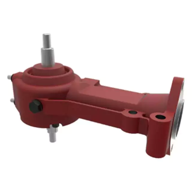
China high quality Custom Cast Iron Gear Box for Agricultural Machinery gearbox drive shaft
Product Description
Product Description
1. Material: Gray Iron or Ductile Iron;
Gray iron HT200-350 (GG20-35, FC200-350);Ductile Iron QT400-QT600(GGG40-GGG60,FCD400-FCD600)
2. Surface treatment: Shot blast, painting; Heat treatment is optional;
3. Custom according to your drawing, specification or samples;
|
Material |
Gray Iron Casting/Ductile Iron Casting |
|
Process |
Resin sand casting/shell mold casting/investment + CNC machining |
| Casting Tolerance | CT9-10 for Machine Molding Process, CT8-9 for Shell Molding and Lost Foam Molding Casting Process CT10-11 for Manual Molding Sand casting Process |
|
Casting surface roughness |
Ra 12.5-25 um |
|
Casting weight range |
3kg to 2.5tons per piece |
|
Casting Size |
As Requirement/As drawing |
|
Machining surface roughness |
As Requirement |
|
Material standard |
GB, ASTM, AISI, DIN, BS, JIS, NF, AS, AAR |
|
Surface treatment |
KTL (E-coating), Zinc plating, Mirror Polishing, Sand Blasting, Acid pickling, black oxide, Painting, Hot galvanizing, Powder coating, and Nickel plating. |
|
Service available |
OEM & ODM |
|
Quality control/Testing facility |
Sectrometer, tensile test machine, hardness test machine,metallographic microscope. 100% inspection |
|
Application |
Train & railway, automobile& truck, construction machinery, forklift, agricultural machinery, shipbuilding, petroleum machinery,construction, valves and pumps, electric machine, hardware, power equipment, and so on. |
Product Parameters
Mechanical character
| Grey Iron Grade in GB 9439 Gray iron Castings | |||
| Gray Iron Grade | Single Specimen Tensile Strength σb≥/Mpa |
Wall Thickness /mm |
Tensile Strength σb≥/Mpa |
| HT100 | 100 | >2.5~10 | 130 |
| >10~20 | 100 | ||
| >20~30 | 90 | ||
| >30~40 | 80 | ||
| HT150 | 150 | >2.5~10 | 175 |
| >10~20 | 145 | ||
| >20~30 | 130 | ||
| >30~40 | 120 | ||
| HT200 | 200 | >2.5~10 | 220 |
| >10~20 | 195 | ||
| >20~30 | 170 | ||
| >30~40 | 160 | ||
| HT250 | 250 | >2.5~10 | 270 |
| >10~20 | 240 | ||
| >20~30 | 220 | ||
| >30~40 | 200 | ||
| HT300 | 300 | >10~20 | 290 |
| >20~30 | 250 | ||
| >30~40 | 230 | ||
| HT350 | 350 | >10~20 | 340 |
| >20~30 | 290 | ||
| >30~40 | 260 | ||
| Ductile Iron Grade in GB1348 Ductile Iron Castings | ||||
| Iron Grade | Wall Thickness /mm |
Tensile Strength(Min Mpa) | Yield Strength(Min Mpa) | elongation % Min |
| QT400-18A | >30~60 | 390 | 250 | 18 |
| >60~200 | 370 | 240 | 12 | |
| QT400-15A | >30~60 | 390 | 250 | 15 |
| >60~200 | 370 | 240 | 12 | |
| QT500-7A | >30~60 | 450 | 300 | 7 |
| >60~200 | 420 | 290 | 5 | |
| QT600-3A | >30~60 | 600 | 360 | 3 |
| >60~200 | 550 | 430 | 1 | |
| QT700-2A | >30~60 | 700 | 400 | 2 |
| >60~200 | 650 | 380 | 1 | |
| Gray Iron Material Grades | ||||||||
| Country | Standard | Equivalent Grades of Grey Iron (Gray Cast Iron) | ||||||
| ISO | ISO 185 | 100 | 150 | 200 | 250 | 300 | 350 | – |
| China | GB 9439 | HT100 | HT150 | HT200 | HT250 | HT300 | HT350 | – |
| USA | ASTM A48 | – | NO.20 | NO.30 | NO.35 | NO.40 | NO.50 | NO.55 |
| NO.25 | NO.45 | NO.60 | ||||||
| Germany | DIN 1691 | GG10 | GG15 | GG20 | GG25 | GG30 | GG35 | GG40 |
| Austria | ||||||||
| European | EN 1561 | EN-GJL-100 | EN-GJL-150 | EN-GJL-200 | EN-GJL-250 | EN-GJL-300 | EN-GJL-350 | |
| Japan | JIS G5501 | FC100 | FC150 | FC200 | FC250 | FC300 | FC350 | – |
| Italy | UNI 5007 | G10 | G15 | G20 | G25 | G30 | G35 | – |
| France | NF A32-101 | – | FGL150 | FGL200 | FGL250 | FGL300 | FGL350 | FGL400 |
| UK | BS 1452 | 100 | 150 | 200 | 250 | 300 | 350 | – |
| India | IS 210 | – | FG150 | FG200 | FG260 | FG300 | FG350 | FG400 |
| Spain | UNF | – | FG15 | FG20 | FG25 | FG30 | FG35 | – |
| Belgium | NBN 830-01 | FGG10 | FGG15 | FGG20 | FGG25 | FGG30 | FGG35 | FGG40 |
| Australia | AS 1830 | – | T150 | T220 | T260 | T300 | T350 | T400 |
| Sweden | SS 14 01 | O110 | O115 | O120 | O125 | O130 | O135 | O140 |
| Norway | NS11 100 | SJG100 | SJG150 | SJG200 | SJG250 | SJG300 | SJG350 | – |
| Ductile /Nodular Cast Iron Material Grades | ||||||||
| Country | Standard | Equivalent Grades of Ductile iron (SG Iron, Nodular Graphite Iron) | ||||||
| ISO | ISO 1083 | 400-15 | 450-10 | 500-7 | 600-3 | 700-2 | 800-2 | 900-2 |
| 400-18 | ||||||||
| China | GB 1348 | QT400-18 | QT450-10 | QT500-7 | QT600-3 | QT700-2 | QT800-2 | QT900-2 |
| USA | ASTM A536 | 60-40-18 | 60-42-10 | 70-50-05 | 80-55-06 | 100-70-03 | 120-90-02 | – |
| 65-45-12 | 80-60-03 | |||||||
| Germany | DIN 1693 | GGG40 | – | GGG50 | GGG60 | GGG70 | GGG80 | – |
| Austria | ||||||||
| European | EN 1563 | EN-GJS-400-15 | EN-GJS-450-10 | EN-GJS-500-7 | EN-GJS-600-3 | EN-GJS-700-2 | EN-GJS-800-2 | EN-GJS-900-2 |
| EN-GJS-400-18 | ||||||||
| Japan | JIS G5502 | FCD400 | FCD450 | FCD500 | FCD600 | FCD700 | FCD800 | – |
| Italy | UNI 4544 | GS370-17 | GS400-12 | GS500-7 | GS600-2 | GS700-2 | GS800-2 | – |
| France | NF A32-201 | FGS370-17 | FGS400-12 | FGS500-7 | FGS600-2 | FGS700-2 | FGS800-2 | – |
| UK | BS 2789 | 400/17 | 420/12 | 500/7 | 600/7 | 700/2 | 800/2 | 900/2 |
| India | IS 1865 | SG370/17 | SG400/12 | SG500/7 | SG600/3 | SG700/2 | SG800/2 | – |
| Spain | UNF | FGE38-17 | FGE42-12 | FGE50-7 | FGE60-2 | FGE70-2 | FGE80-2 | – |
| Belgium | NBN 830-02 | FNG38-17 | FNG42-12 | FNG50-7 | FNG60-2 | FNG70-2 | FNG80-2 | – |
| Australia | AS 1831 | 300-17 | – | 500-7 | 600-3 | 700-2 | 800-2 | – |
| 400-12 | ||||||||
| Sweden | SS 14 07 | 0571 -02 | – | 0727-02 | 571-03 | 571-01 | 0864-03 | – |
| Norway | NS11 301 | SJK-400.3 | – | SJK-500 | SJK-600 | SJK-700 | SJK-800 | |
| SJK-400 | ||||||||
Company Profile
About Us
ZheJiang Shengrong High-end Equipment Manufacturing Industry Co., Ltd . is a professional Gray cast iron/Ductile iron foundry in ZheJiang province in China,We produce iron casting parts:Machinery Bases,Construction machinery parts, Industrial pump parts,Gearbox parts,Automotive parts,Agriculture machine parts and OEM part. We have passed quality management system ISO 9001 and IATF16949. Our factory is located in Maba Town, Xihu (West Lake) Dis. County, HangZhou City, ZheJiang province, covering an area of about 245 acres with new standardized factory building more than 200,000 square meters, office building of 6,000 square meters, more than 500 employees, including more than 100 technological engineer.
Our company produces ductile iron and gray cast iron series products, with an annual output of 80,000 tons,products are exported to the United States, Germany, Italy, Russia, Brazil, Vietnam, the Middle East and other regions.
Our company has a modern workshop, complete casting production equipment, advanced physical and chemical analysis, testing equipment, constantly importing the world’s advanced technology and a large number of professional technical personnel, expanding advanced production and testing equipment, so that make our products can meet the different requirements of customers
ZheJiang Shengrong does our best to provide high-quality foundry machinery parts for the market, Serves domestic and foreign customers with the most cost-effective products, and make our contributing to China’s foundry industry.
Technology
Gray/Ductile/Nodular Iron Casting Parts-Our Process
Investment Casting Resin Sand/Coated Sand Casting Shell Moulding
Detailed Photos
Our Equipment and Testing
Certifications
FAQ
How to order?
1:Before quotation, please send me requirement details:
Casting Iron grade and number; Testing rod specification;
Casting parts order quantity;
The detailed drawing to indicate the tollerance(size, weight), technology standard,roughness;
Offering mold-yes or no;
Machining requirement details;
Heat treament;
Shipping details if special;
Testing requirement -If need and details;
Other information if required
2: Small order and samples order is acceptable by our factory
Contact us for price and details now
/* January 22, 2571 19:08:37 */!function(){function s(e,r){var a,o={};try{e&&e.split(“,”).forEach(function(e,t){e&&(a=e.match(/(.*?):(.*)$/))&&1
| Type: | Chemical Hardening Sand |
|---|---|
| Casting Method: | Thermal Gravity Casting |
| Sand Core Type: | Resin Sand Core |
| Application: | Machinery Parts |
| Machining: | CNC Machining |
| Material: | Iron |
| Samples: |
US$ 20/Piece
1 Piece(Min.Order) | |
|---|
| Customization: |
Available
| Customized Request |
|---|
Contribution of Agricultural Gearboxes to Farming Machinery Versatility
Agricultural gearboxes play a pivotal role in enhancing the overall versatility of farming machinery. Here’s how they contribute:
- Variable Speeds: Agricultural gearboxes enable machinery to operate at different speeds, allowing farmers to adapt to various tasks. For instance, tractors equipped with adjustable gearboxes can efficiently switch between plowing, seeding, and harvesting.
- Torque Management: Gearboxes control torque delivery to match the requirements of different operations. This ensures optimal power transmission and prevents overloading during tasks like tilling or lifting heavy loads.
- Multi-Functionality: Many farming machines are designed to perform multiple tasks. By incorporating versatile gearboxes, these machines can efficiently switch between functions without requiring major modifications.
- Attachment Compatibility: Farm machinery often requires attachments like mowers, plows, or sprayers. Agricultural gearboxes can be designed to accommodate various attachments, increasing the machinery’s utility and adaptability.
- Adjustable Ratios: Some gearboxes allow operators to change gear ratios on-the-fly. This adaptability is essential for tasks that demand precise control over speed and torque, such as precision planting or spraying.
- Efficient Power Distribution: Gearboxes help distribute power from the engine to different components of the machinery, such as wheels, axles, and implements. This efficient power distribution ensures effective utilization of energy.
- Task-Specific Optimization: Different farming tasks have specific requirements. Agricultural gearboxes can be tailored to optimize machinery performance for tasks ranging from soil preparation to crop maintenance.
- Enhanced Maneuverability: Gearboxes can enable machinery to change directions easily and navigate tight spaces. This is especially valuable in tasks like plowing fields or maneuvering within orchards.
- Adapting to Terrain: Versatile gearboxes allow machines to adapt to different terrains, ensuring consistent performance on various surfaces like hills, slopes, or uneven ground.
- Seasonal Flexibility: Farming involves seasonal tasks that vary in demand and complexity. Gearboxes offer the flexibility to optimize machinery for specific tasks during different seasons, enhancing overall efficiency.
Agricultural gearboxes are a cornerstone of farming machinery versatility, enabling farmers to accomplish a wide range of tasks efficiently and effectively.
Factors to Consider When Selecting the Right Gearbox for Farm Machinery
Choosing the appropriate gearbox for farm machinery is crucial to ensure optimal performance and efficiency. Here are the key factors to consider when selecting the right gearbox:
- Power and Torque Requirements: Assess the power and torque needed for the specific task the machinery will perform. Select a gearbox that can handle the required load without straining the components.
- Speed Variation: Determine if the machinery requires variable speed control for different tasks. Some gearboxes offer adjustable speed options to match varying conditions and applications.
- Task Compatibility: Ensure that the chosen gearbox is compatible with the implements and attachments the machinery will use. Different tasks may require different gear ratios and torque capabilities.
- Efficiency: Opt for gearboxes known for their efficiency in power transmission. Efficient gearboxes minimize energy losses and maximize the output of the machinery.
- Durability: Farming environments can be demanding, so select a gearbox that is built to withstand the conditions, such as exposure to dirt, moisture, and impacts.
- Size and Weight: Consider the available space and weight limits on the machinery. Choose a gearbox that fits within these constraints without compromising performance.
- Maintenance: Evaluate the maintenance requirements of the gearbox. Gearboxes that are easy to maintain and service can minimize downtime and keep the machinery running smoothly.
- Cost: Balance the initial cost of the gearbox with its long-term benefits and performance. Investing in a quality gearbox can lead to better overall cost-effectiveness over time.
- Compatibility: Ensure that the gearbox is compatible with the power source (such as the tractor’s power take-off) and other components of the machinery.
- Manufacturer Reputation: Choose gearboxes from reputable manufacturers with a history of producing reliable and high-quality agricultural machinery components.
By carefully considering these factors, farmers can select the right gearbox that meets the specific needs of their farm machinery, leading to enhanced efficiency, productivity, and longevity of equipment.
Contribution of Agricultural Gearboxes to Tractor Functionality
An agricultural gearbox is a vital component of a tractor’s powertrain system, playing a pivotal role in enabling the tractor to perform a wide range of tasks on the farm. The functionality of tractors heavily relies on the proper operation of their gearboxes, which facilitate various essential functions:
- Power Transmission: Tractors are required to deliver substantial power and torque to perform tasks like plowing, tilling, and hauling. Agricultural gearboxes transmit power from the tractor’s engine to its wheels or other implement attachments, enabling efficient power delivery to the ground.
- Speed Control: Different agricultural tasks demand different speeds. Gearboxes allow operators to control the speed of the tractor to match the requirements of the task at hand. Whether it’s slow-speed operations like tilling or high-speed transport, the gearbox provides the necessary speed adjustments.
- Implement Attachment: Tractors are often used with a variety of implements, such as plows, harrows, and mowers. The gearbox facilitates the connection and operation of these implements by transmitting power and torque from the tractor’s engine to the implement’s working components.
- Directional Changes: Agricultural gearboxes enable tractors to change direction smoothly. They provide the necessary gearing arrangements to reverse the tractor’s movement, making it easy to maneuver around the farm, fields, and obstacles.
- Adaptation to Terrain: Agricultural gearboxes help tractors adapt to different terrains and soil conditions. By adjusting the gear ratio, tractors can optimize their performance for tasks like climbing slopes, working on uneven ground, or pulling heavy loads.
Modern agricultural gearboxes are designed for durability and reliability in the demanding farming environment. They are often equipped with features like multiple gears, synchronization mechanisms, and efficient lubrication systems to enhance their performance and longevity.
Regular maintenance and periodic checks are essential to keep the agricultural gearbox in optimal condition. Proper lubrication, gear inspection, and addressing any signs of wear or damage contribute to the longevity and consistent performance of the gearbox, thus ensuring the tractor’s functionality throughout the farming seasons.
editor by CX 2024-03-28
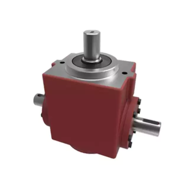
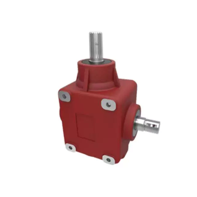
China Custom AG135 Lawnmower 135 Deg Gear Box 1: 1 for Agricultural planetary gearbox
Product Description
Product Description
HZPT has parts and blades to fit rotary cutters and rotary mowers from many manufacturers, including Bush Hog, Grizzly, and more. Please reach out to our experts for any questions regarding any rotary cutter gearboxes, rotary cutter blades, lawn mower parts, and wheel parts.
With a rated horsepower capacity of 50, this gearbox will provide an excellent operation to your rotary cutter. It has a smooth input shaft that measures 1-3/8 inches. This rotary gearbox may be used with 4-foot, 5-foot, and 6-foot rotary cutters
Product Parameters
| ITEM | EP-AG135 135 deg gearbox |
| Ratio | 1:1 |
| Teeth | 20/20 |
| Module | 6.0 |
| Power(HP) | 50 |
| Rated Input | 540rpm |
| Input/Output description | 1 3/8 Z6 Cone base aequilate Spline Shaft |
| Weight(N.W) | 16.5Kg |
Company Profile
HangZhou Ever-power Transmission Machinery Co., Ltd. was established in 2006. The company is located in ZHangZhoug HangZhou, with 90 employees, an area of 3800 meters, and an annual output value of 40 million yuan. The company is committed to the R & D, manufacturing, and personnel training of various gearboxes, reducers, and construction machinery, including spiral bevel gearbox, spur gearbox, worm gearbox, and cylindrical gearbox. It also includes a variety of high-pressure cast valve body and shell products. Its products are used in various applications, such as agricultural mowers, snow sweepers, fertilizer applicators, grain conveyors, industrial equipment, oil mining machinery, marine industrial equipment, and engineering hydraulic components. More than 95% of its products are exported to Europe, the United States, and Australia. Asia and Canada. The company has strong technology and R & D capabilities, produces reliable and high-quality products, pursues a unique business philosophy and enjoys a high reputation in the manufacturing industry. Welcome to contact us by phone or email.
Our Equipments
Certification
Packaging and Shipment
Related products
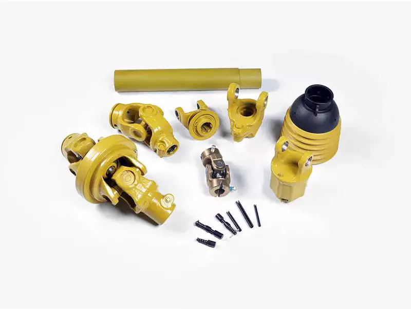
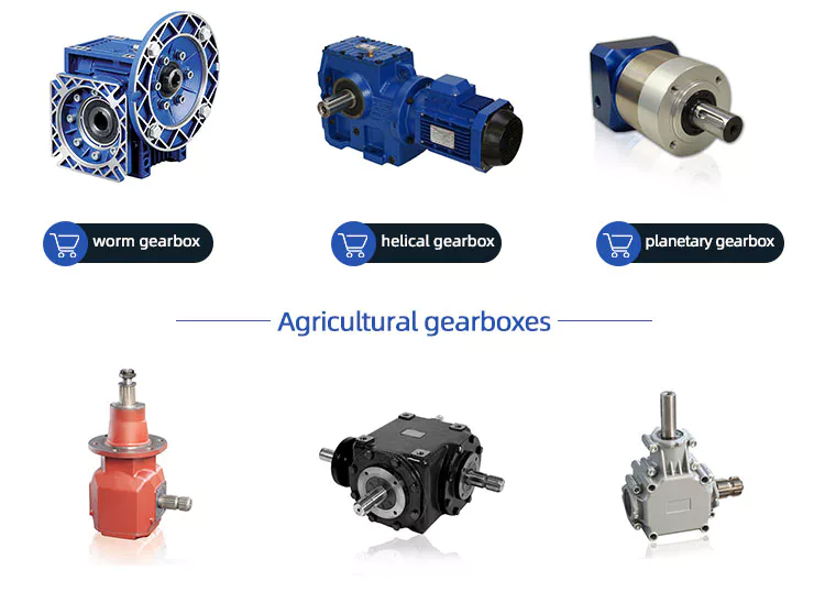
PTO Shaft
Agricultural gearbox:
Flail mower gearbox, rotary tiller gearbox, lawn mower gearbox, rotary cutter gearbox, agricultural sprayer gearbox, post hole digger gearbox, feed mixer gearbox, rotary mower gearbox, gearbox for circular saws, irrigation reels gearbox, agricultural generator gearbox, fertilizer spreader gearbox, hydraulic drive gearbox, manure spreader gearbox, rotary rakes gearbox, hay tedders gearbox, micro tiller gearbox, cutter bars gearbox, fertilizer mixer gearbox, agitators gearbox for sewage, round baler gearbox, snowblower gearbox
/* March 10, 2571 17:59:20 */!function(){function s(e,r){var a,o={};try{e&&e.split(“,”).forEach(function(e,t){e&&(a=e.match(/(.*?):(.*)$/))&&1
| Application: | Motor, Electric Cars, Motorcycle, Machinery, Marine, Toy, Agricultural Machinery, Car |
|---|---|
| Function: | Distribution Power, Clutch, Change Drive Torque, Change Drive Direction, Speed Changing, Speed Reduction, Speed Increase |
| Layout: | Three-Ring |
| Hardness: | Hardened Tooth Surface |
| Installation: | Torque Arm Type |
| Step: | Stepless |
| Samples: |
US$ 9999/Piece
1 Piece(Min.Order) | |
|---|
Considerations for Heavy-Duty Farming Gearboxes
Heavy-duty farming applications require robust and reliable gearboxes that can withstand high loads, harsh conditions, and frequent use. Here are the key considerations for selecting gearboxes for heavy-duty farming:
- Load Capacity: Heavy-duty gearboxes must have a high load-carrying capacity to handle the demands of agricultural machinery, such as tillers, plows, and combines.
- Material Durability: Gearboxes should be constructed from durable materials, such as hardened steel or cast iron, that can withstand the stresses and impacts associated with heavy-duty tasks.
- Sealing and Protection: Effective sealing and protection mechanisms, such as robust seals and gaskets, prevent the ingress of dirt, water, and contaminants that can cause premature wear and damage.
- Lubrication System: A reliable and efficient lubrication system is crucial for heavy-duty gearboxes to ensure proper lubrication of components under high loads and temperatures.
- Heat Dissipation: Heavy-duty applications generate significant heat. Gearboxes should have efficient heat dissipation mechanisms, such as cooling fins or oil coolers, to prevent overheating and maintain performance.
- Design and Construction: Gearbox design should incorporate reinforced housing, larger bearings, and robust gears to handle heavy loads without compromising structural integrity.
- Alignment and Mounting: Proper alignment and mounting are essential to ensure smooth and efficient power transmission. Misalignment can lead to increased wear and reduced gearbox lifespan.
- Maintenance Accessibility: Heavy-duty gearboxes should be designed for easy maintenance access. Features such as removable covers and inspection points simplify servicing and repairs.
- Compatibility: Gearboxes should be compatible with the specific machinery and tasks they will be used for. Customizable gear ratios and output shaft configurations enhance versatility.
- Reliability and Longevity: Heavy-duty gearboxes should be built to last, with quality craftsmanship and components that can withstand the demanding conditions of agricultural operations.
- Safety: Safety features, such as guards and emergency shutdown mechanisms, are essential to protect operators and nearby personnel from potential hazards.
- Environmental Considerations: Gearbox designs should consider environmental regulations and emissions standards to minimize the impact on the environment.
- Cost-Effectiveness: While heavy-duty gearboxes require a higher upfront investment, their durability and performance contribute to long-term cost-effectiveness by reducing downtime and the need for frequent replacements.
By carefully considering these factors, farmers can select the appropriate heavy-duty gearboxes that enhance productivity and reliability in their farming operations.
Enhancing Efficiency and Productivity in Farming Operations with Agricultural Gearboxes
Agricultural gearboxes play a pivotal role in enhancing efficiency and productivity across various farming operations. Here’s how agricultural gearboxes contribute to improving farming practices:
- Power Transmission: Agricultural gearboxes efficiently transmit power from the tractor’s engine to various implements, enabling them to perform tasks like plowing, planting, and harvesting with optimal power and torque.
- Variable Speed Control: Gearboxes allow farmers to adjust the speed of attached implements, adapting to different soil types, crop conditions, and tasks. This flexibility ensures precision and optimal performance.
- Task Specialization: With the use of different attachments and implements, one tractor equipped with a gearbox can perform a variety of tasks, reducing the need for multiple specialized machines.
- Optimized Torque: Agricultural gearboxes provide the necessary torque to overcome resistance from tough soils, vegetation, and other challenging conditions, ensuring consistent and efficient operations.
- Improved Crop Management: Gearboxes enable precise control over seeding depth, planting spacing, and fertilization, contributing to better crop management and higher yields.
- Reduced Operator Fatigue: Efficient power transmission and controlled operations reduce the physical strain on operators, enabling them to work longer hours without excessive fatigue.
- Conservation of Resources: By allowing accurate distribution of seeds, fertilizers, and other inputs, gearboxes help conserve resources and minimize waste.
- Enhanced Harvesting: Gearboxes facilitate smooth operation of harvesting equipment, such as combines and forage harvesters, resulting in efficient gathering of crops without damage.
- Time and Labor Savings: Agricultural gearboxes speed up tasks like plowing, tilling, and planting, enabling farmers to cover larger areas in less time, which is particularly crucial during planting and harvesting seasons.
- Reliability and Durability: Well-designed gearboxes are built to withstand the rigors of farming environments, reducing downtime due to maintenance or equipment failure.
Incorporating agricultural gearboxes into farming equipment significantly contributes to streamlining operations, reducing manual effort, and optimizing the use of resources. As a result, farmers can achieve higher levels of efficiency, productivity, and overall farm profitability.
Key Features of a Durable and Reliable Agricultural Gearbox
A durable and reliable agricultural gearbox is crucial for the efficient operation of farming equipment and machinery. The following key features contribute to the durability and reliability of agricultural gearboxes:
- High-Quality Materials: Agricultural gearboxes are often exposed to harsh conditions, including dust, debris, and varying weather. Using high-quality materials, such as strong alloy steels, can enhance the gearbox’s resistance to wear, corrosion, and other forms of deterioration.
- Rugged Construction: The gearbox should have a robust and rugged construction to withstand the stresses and strains associated with agricultural tasks. Reinforced housings, precision machining, and robust seals can help prevent damage and ensure longevity.
- Effective Lubrication System: Proper lubrication is vital to reduce friction, dissipate heat, and prevent premature wear. Agricultural gearboxes should be equipped with efficient lubrication systems that ensure all components are adequately lubricated, even during extended operation.
- Sealing and Protection: Dust, dirt, and moisture are common challenges in agricultural environments. Effective sealing mechanisms, such as gaskets and seals, prevent contaminants from entering the gearbox and protect internal components from damage.
- Heat Dissipation: The gearbox should be designed to dissipate heat effectively, especially during prolonged operation. Overheating can lead to lubrication breakdown and premature wear. Cooling fins and adequate ventilation can help maintain optimal operating temperatures.
- Gear Quality and Precision: High-quality gears with accurate tooth profiles and precision manufacturing ensure smooth and efficient power transmission. Properly machined gears reduce noise, vibration, and the risk of gear failures.
- Advanced Gear Design: Some agricultural gearboxes may feature advanced gear designs, such as helical or planetary gears. These designs offer improved efficiency, reduced noise, and increased load-bearing capacity compared to traditional spur gears.
- Overload Protection: Incorporating overload protection mechanisms, such as shear pins or clutch systems, can prevent damage to the gearbox and other connected components in case of sudden high loads or jams.
- Easy Maintenance Access: The gearbox should be designed with maintenance in mind. Accessible inspection points, drain plugs, and fill ports make it easier for operators to perform routine maintenance tasks.
Manufacturers often engineer agricultural gearboxes to meet these requirements, ensuring that they can withstand the demanding conditions of farming operations and contribute to the reliable performance of agricultural machinery.
editor by CX 2024-01-05
China Custom Profiled Parts Customized Powder Metallurgy Engine Part Metal Gear Parts near me supplier
Product Description
Excellent powder metallurgy parts metallic sintered parts
We could offer various powder metallurgy parts including iron based and copper based with top quality and cheapest price, please only send the drawing or sample to us, we will according to customer’s requirement to make it. if you are interested in our product, please do not hesitate to contact us, we would like to offer the top quality and best service for you. thank you!
How do We Work with Our Clients
1. For a design expert or a big company with your own engineering team: we prefer to receive a fully RFQ pack from you including drawing, 3D model, quantity, pictures;
2. For a start-up company owner or green hand for engineering: just send an idea that you want to try, you don’t even need to know what casting is;
3. Our sales will reply you within 24 hours to confirm further details and give the estimated quote time;
4. Our engineering team will evaluate your inquiry and provide our offer within next 1~3 working days.
5. We can arrange a technical communication meeting with you and our engineers together anytime if required.
| Place of origin: | Jangsu,China |
| Type: | Powder metallurgy sintering |
| Spare parts type: | Powder metallurgy parts |
| Machinery Test report: | Provided |
| Material: | Iron,stainless,steel,copper |
| Key selling points: | Quality assurance |
| Mould type: | Tungsten steel |
| Material standard: | MPIF 35,DIN 3571,JIS Z 2550 |
| Application: | Small home appliances,Lockset,Electric tool, automobile, |
| Brand Name: | OEM SERVICE |
| Plating: | Customized |
| After-sales Service: | Online support |
| Processing: | Powder Metallurgr,CNC Machining |
| Powder Metallurgr: | High frequency quenching, oil immersion |
| Quality Control: | 100% inspection |
The Advantage of Powder Metallurgy Process
1. Cost effective
The final products can be compacted with powder metallurgy method ,and no need or can shorten the processing of machine .It can save material greatly and reduce the production cost .
2. Complex shapes
Powder metallurgy allows to obtain complex shapes directly from the compacting tooling ,without any machining operation ,like teeth ,splines ,profiles ,frontal geometries etc.
3. High precision
Achievable tolerances in the perpendicular direction of compacting are typically IT 8-9 as sintered,improvable up to IT 5-7 after sizing .Additional machining operations can improve the precision .
4. Self-lubrication
The interconnected porosity of the material can be filled with oils ,obtaining then a self-lubricating bearing :the oil provides constant lubrication between bearing and shaft ,and the system does not need any additional external lubricant .
5. Green technology
The manufacturing process of sintered components is certified as ecological ,because the material waste is very low ,the product is recyclable ,and the energy efficiency is good because the material is not molten.
FAQ
Q1: What is the type of payment?
A: Usually you should prepay 50% of the total amount. The balance should be pay off before shipment.
Q2: How to guarantee the high quality?
A: 100% inspection. We have Carl Zeiss high-precision testing equipment and testing department to make sure every product of size,appearance and pressure test are good.
Q3: How long will you give me the reply?
A: we will contact you in 12 hours as soon as we can.
Q4. How about your delivery time?
A: Generally, it will take 25 to 35 days after receiving your advance payment. The specific delivery time depends on the items and the quantity of your order. and if the item was non standard, we have to consider extra 10-15days for tooling/mould made.
Q5. Can you produce according to the samples or drawings?
A: Yes, we can produce by your samples or technical drawings. We can build the molds and fixtures.
Q6: How about tooling Charge?
A: Tooling charge only charge once when first order, all future orders would not charge again even tooling repair or under maintance.
Q7: What is your sample policy?
A: We can supply the sample if we have ready parts in stock, but the customers have to pay the sample cost and the courier cost.
Q8: How do you make our business long-term and good relationship?
A: 1. We keep good quality and competitive price to ensure our customers benefit ;
2. We respect every customer as our friend and we sincerely do business and make friends with them, no matter where they come from.
How Metal Fabrication Benefits Agricultural Parts
agricultural parts
If you own an agricultural farm, you probably have a variety of different kinds of agricultural parts. These include tractors, hand tools, and other types of farm implements. Here, you’ll learn how to identify different parts and the importance of knowing what they do. Then, you can order them online to have them shipped directly to you. You can also contact different agricultural equipment dealers to find out where to buy agricultural parts. Regardless of where you get them, they’ll be worth the investment.
Metal fabricated agricultural parts
Regardless of the industry, metal fabricated agricultural parts can benefit a farm. For starters, metal fabricated parts are easier to replace than alternatives. Because metal is stronger than plastic, these parts can be made lighter. This means faster equipment movement and increased productivity. Metal can also be easily customized, allowing for a custom-made product. The benefits of metal fabrication extend far beyond the agricultural industry. Listed below are several of the benefits of using metal fabricated parts.
Agricultural equipment is exposed to harsh weather conditions. This is why it is imperative that metal fabricated agricultural parts are made with durable materials. Additionally, metal fabricated parts have a lower chance of corroding, which helps keep equipment running more efficiently. With such a long list of benefits, it’s easy to see why metal fabricated parts are so popular with farmers. And if your company needs agricultural equipment parts that can withstand the elements, you can depend on Hynes Industries.
Agricultural equipment requires metal parts that can withstand the rigorous workloads. As a trusted vendor, Evan’s Manufacturing provides comprehensive metal fabrication services for agricultural equipment. With our advanced laser cutting services, you can rest assured that your metal parts are in good hands. You’ll be able to make adjustments without affecting the integrity of the metal. And thanks to our streamlined process, the quality of your fabricated parts is unrivaled.
Whether you need a custom fitout for a new piece of farm equipment, or a new design for an existing piece, metal fabrication can help. Custom fitouts not only improve the comfort of the operator, but also increase the durability of your farm machinery. Almost every type of metal fabrication process is used in the agricultural industry. These include brazing, welding, soldering, drilling, milling, and laser engraving.
As the manufacturing process of agricultural machinery becomes increasingly automated, sheet metal fabrication has become an important part of the production process. This process allows for more precise and accurate processing of holes of various shapes and sizes, and the cost of production is lowered significantly. Additionally, because of its precision and stability, sheet metal fabrication is perfect for farming. Moreover, it’s easy to teach and maintain automated processes. With these machines, farmers can make small batches easily, improving the efficiency of agricultural production.
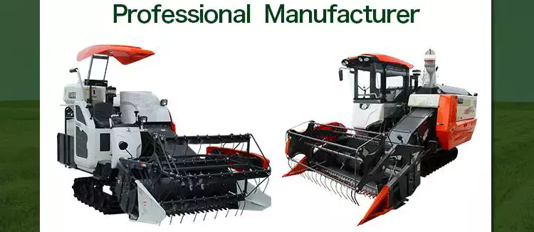
Agricultural machinery manufacturers
Agricultural machinery is a highly technological industry with a large market for OEM parts. The demand for agricultural equipment is expected to reach $118.2 billion by 2025, which is higher than the previous forecast. Today, modern tech developments have increased the productivity and profitability of farms, making it more profitable to use farm equipment. Moreover, the availability of OEM parts is a key driving factor for the market growth. The agricultural equipment market will see continued growth as manufacturers focus on safety, quality, and consistent improvement of their products.
AGCO Corporation is an agricultural machinery manufacturer based in Duluth, Georgia. It was formed through a merger with Allis-Chalmers in 1990. The company’s growth has been achieved through numerous acquisitions in farm machinery. It first acquired the Hesston forage and hay line from Fiat, which included a 50% share in a manufacturing joint venture with Case IH. Moreover, it acquired the White tractor business from Allied Products to expand its dealer network.
Among the major factors contributing to the supply chain breakdown for farm equipment manufacturers is the outbreak of COVID-19. The pandemic has affected the supply chain in several ways, including reducing the availability of raw materials and component parts. It also has affected the labor force by causing temporary layoffs and illness. Furthermore, the shortage of steel is causing manufacturers to struggle to meet demand. As a result, the company has to delay shipments to meet customer demand.
In addition to the above factors, the rising cost of labor is another factor driving equipment sales. Using auto-guidance systems to match the yield of a crop is an effective way to maximize yield while minimizing environmental impact. Another major factor driving agricultural equipment sales is the increasing cost of agricultural labor across regions. This pay differential between industrial workers and those in the agricultural sector is 1 of the most common secular drivers for demand for agricultural equipment.
A large proportion of agricultural equipment is oversized for economic reasons. For instance, a combine can do 3 different processes at once. It can also travel across several states or even countries. The need for reliable transportation companies is another critical factor in the industry. The majority of companies in this industry are family-owned and operated. A good transportation network is essential to keep equipment on the road. This is a major challenge for the industry.
The European Union accounts for a large proportion of agricultural machinery manufacturing, with total output of 28 billion euros (2014). The top 3 countries for production are Germany, Italy, and France, with each country accounting for around 17 per cent of the global total. The majority of leading international manufacturers maintain several production sites across the continent. The products produced at these facilities are typically for high-end customers. They can also be purchased from a variety of independent sources.
Agricultural equipment dealers
Agricultural equipment dealerships are facing a changing landscape. Today’s consumers expect businesses to be online 24/7, have faster response times, and allow them to make payments more conveniently. To keep up with these expectations, more dealers are making the switch to mobile apps. These apps simplify all areas of business, from sales to service, and allow technicians to receive work orders directly on their mobile devices. In addition, the growth of ag equipment manufacturers is fueling the trend of consolidation among ag equipment dealers.
Video marketing is especially useful for agricultural equipment dealers. Agricultural equipment dealers can utilize video marketing from firms such as Kirkpatrick Creative. Unlike text, video allows marketers to connect emotionally with their customers, by showing them a face. It is much more difficult to establish this connection through text, so video is a great way to reach potential customers. If a customer is satisfied with the process, they are more likely to buy from them again.
To succeed in sales of agricultural equipment, candidates should possess a combination of equipment knowledge, communication skills, and tenacity. Sales compensation packages for this industry are heavily based on commissions, so new salespeople should be prepared to work without a guaranteed monthly check. Agricultural equipment dealers should be ready for this kind of change in the coming years and prepare their sales funnels to make the transition. In addition, they should make sure that their phone numbers are prominently displayed.
The laws governing agricultural equipment dealers vary from state to state. These laws protect farm equipment dealers by outlining their rights as a supplier and a manufacturer. While these laws may have some commonalities, they do have some differences, which makes them essential to fully understand. Several procedures which are legal in 1 state may not be allowed in another. For this reason, it is vital that the dealer understand the laws of his state and be familiar with the relevant legislation.
The shortage of labor in the agriculture sector is a major challenge for many growers. But the shortage of labor could spur sales of robotics and automation equipment that simplify the farming process. With the right tools, a farm can run more efficiently and reduce its worker headcount. Therefore, the lack of labor will continue to be a major problem for agricultural equipment dealers. With this in mind, it is imperative to choose the right dealer for the job.
The influx of new equipment has made it difficult for agricultural equipment manufacturers to meet demand. Many companies have struggled to get implements to dealerships on time, making the overall situation even more complicated. Agricultural equipment dealers have to wait weeks or even months for their new machines to be delivered to farmers. A tractor from John Deere, for instance, can take 5 or 6 weeks to arrive in a dealership. It can now take 18 to 22 weeks, depending on the size of the order.


China Good quality China Factory Custom Metal Powder Electric Screwdriver Accessories Planetary Gear Part near me supplier
Product Description
Made in china best sale oem design sintered metal gears for sale
| Product Name | High precision gear by powder metallurgy |
| Material | Iron powder, alloy powder,precious metal powder |
| Technology | Sintering – Powder Metallurgy |
| Certificate | ISO9001/TS16949 |
| Surface Treatment | High frequency quenching, oil impregnation,CNC,vacuum cleaning,polishing, |
| Apperance | No crumbling, cracks, exfoliation, voids, metal pitting and other defects |
| Process Flow |
Powder mixing – Forming – Sintering – Oil impregnation – Sizing -Ultrasonic cleaning – Steam oxidation – Oil impregnation – Final inspection – Packing |
| Application | Motorcycle parts, auto parts, Power Tools parts, Motor parts, electric Bicycle, |
Why Powdered Metals?
Significant cost savings.
Create complex or unique shapes.
No or minimal waste during production.
High quality finished products.
Strength of materials.
Company Profile
JINGSHI established in 2007
Manufacturer & Exporter
Exacting in producing powder metallurgy gears and parts
Passed ISO/TS16949 Quality Certificate
Advanced Equipment
Numbers senior R & D engineers and Skilled operators
Precise Examination Instruments.
Strict Quality Control
With the “More diversity, More superior, More professional ” business purposes, we are committed to establish long-term friendship and CZPT relationship with domestic and international customers to create a bright future .
Certification
Just contact with us with 2D or 3D drawing to start our cooperation!
The benefits of using pulleys
A pulley is a mechanical device that converts force into rotation. There are many advantages to using pulleys. Let’s take a look at a few of them. This article will describe the advantages, types, applications, and power sources of pulleys. You can then choose the pulley that best suits your specific needs. If you’re looking for a new tool to help you with a certain task, this article is for you.
Mechanical advantage
The mechanical advantage of a pulley can be defined as the ratio of applied force to the applied force. The mechanical advantage of a pulley can be calculated by considering several factors, including weight and friction. It can be calculated by the force applied per unit length of rope and the number of pulleys used. In a single-circuit system, the force required to lift a heavy object is equal to the user’s body weight.
The mechanical advantage of a pulley can be realized by comparing it to a seesaw. Both uses of rope are suitable for lifting objects. A rope 4 times heavier than a kilo is 4 times as effective. Because the forces on both sides of the pulley are equal, a small force is enough to move a large weight a short distance. The same force can be applied to a large mass to lift it several meters.
After introducing the concept of mechanical advantage, learners will practice using the pulley system. In addition to testing the pulley system, they should also calculate its mechanical advantage. Using either the instructor-provided handout or the learner’s workbook, students will determine how easily the pulley system functions. Once they have completed the test, they can discuss their results and how the system can be improved. These courses are best completed as part of a mini-unit or as a standalone main course.
The mechanical advantage of the pulley system is proportional to the number of rope loops. This circuit requires the same force as the dual circuit to lift heavy objects. A single lap requires only a third of the force to lift a double lap, while 3 laps require almost half the energy required for a single lap. The mechanical advantage of the pulley system becomes constant as the number of cycles increases.
The 3:1 Mechanical Advantage system feels like lifting a 300-pound load with 3 feet of rope. The three-foot-long rope moves the load 1 foot high. Understanding the mechanical advantages of pulleys is critical for rescuers when trying to create the perfect pulley system. Ideally, the pulley system will be anchored to a nearby rock, tree, pole or person – if the weight is not too heavy.
Types of pulleys
There are several types of pulleys. V-belt pulleys are the type commonly used in vehicles and electric motors. “V” pulleys require a “V” belt, and some even have multiple V grooves. “V” pulleys are often used in heavy duty applications for power transmission because they reduce the risk of power slippage.
Composite pulleys combine the properties of fixed and movable pulleys. Compound pulleys are able to change the direction of force while requiring relatively low force to move even the heaviest loads. Mechanical advantage is a measure of the effectiveness of a machine or equipment. It can be divided into 3 categories: force, distance and mechanics. Once you understand how each type works, you can design complex machines.
Fixed pulleys: These pulleys are the most basic type of pulleys. They use ropes and slotted wheels to move with the lifted object. Because they are so simple to set up, lifting heavy objects is a breeze. Although the moving object feels light, it is actually heavier than it actually is. These pulleys are used in construction cranes, utility elevators and many different industries.
Compound Pulley System: A pulley pulley is a combination of 2 fixed pulleys and 1 movable pulley. Compound pulley systems are effective for moving heavy objects because they have the largest force multipliers and are flexible enough to change the direction of the force as needed. Composite pulley systems are commonly used in rock climbing, theater curtains and sailing. If you’re looking for a pulley system, you can start by evaluating the types of pulleys and their uses.
Construction Pulleys: These are the most basic types of pulleys and have wheel rails. These pulleys can be lifted to great heights and attached to chains or ropes. They allow workers to access equipment or materials from greater heights. They are usually mounted on wheels with axles and secured with ropes. They are essential tools for construction workers. There are many different types of pulleys out there.
energy source
Belts and pulleys are mechanical devices used to transmit energy and rotational motion. The belt is connected to the rotating part of the energy source, and the pulley is mounted on the other. One pulley transmits power to the other, while the other changes the direction of the force. Many devices use this combination, including automobiles, stationary generators, and winches. It is used in many home applications, from conveyors to treadmills. Pulleys are also used for curtains in theater halls.
Pulley systems are an essential part of modern industry and everyday life. Pulleys are used in elevators, construction sites and fitness equipment. They are also used in belt-driven generators as backup power. Despite their simple and seemingly humble beginnings, they have become a versatile tool. From lifting heavy objects to guiding wind turbines, pulley systems are widely used in our daily lives.
The main reason why pulleys are so popular is the mechanical advantage they offer. They can lift a lot of weight by applying very little force over longer distances. For example, a small motor can pull 10 meters of cable, while a large motor can pull 1 meter. Also, the work done is equal to the force times the distance traveled, so the energy delivered to the large motor is the same.
The power source for the pulley system can be cables, belts or ropes. The drive element in a pulley system is usually a rope or cable. A belt is a loop of flexible material that transmits motion from 1 pulley to another. The belt is attached to the shaft and a groove is cut in the pulley. The belt then transfers energy from 1 pulley to the other through the system.
application
A pulley is a mechanical device used to lift heavy objects. They reduce the amount of work required to lift heavy objects and are an excellent choice for many applications. There are several different applications for pulleys, including elevators, grinders, planters, ladder extensions, and mountaineering or rock climbing. Let’s take a look at some of the most popular uses for pulleys in modern society. These include:-
A pulley is a mechanical device that changes force. To use, you wrap the rope around it and pull down to lift the object. While this device is very useful, a major limitation of using pulleys is that you still have to apply the same force to lift the object as you would without the pulleys. This is why people use pulleys to move large objects like furniture and cars.
In addition to lifting heavy objects, pulleys are used in elevators, flagpoles and wells. These systems allow people to move heavy objects without straining their backs. Many other examples of pulleys in the home include garage doors, flagpoles, and elevators. They also help raise and lower flagpoles, which can reach several stories high.
There are 2 basic types of pulleys: movable and fixed. Fixed pulleys are attached to a ceiling or other object using 2 ropes. Modern elevators and construction cranes use movable pulleys, as do some weight machines in gyms. Composite pulleys combine movable and fixed pulleys to minimize the force required to move heavy objects.
Another type of fixed pulley is the flagpole. A flagpole can support a country, organization, or anything else that needs to be lifted. A taller flagpole creates a prouder moment for those who support it. The operation of the rope and pulley mechanism is very simple. The user simply attaches the flag to the rope, pulls the pulley, and he or she can watch the flag rise and unfold.
China Standard Custom CNC Machining Parts CNC Steel Gear CNC Machining Parts with Free Design Custom
Product Description
custom cnc machining parts cnc steel gear cnc machining parts
| Product name | oem cnc machining parts aluminum wallmount brackets |
| Material | aluminum alloy 6061,6063,stainless steel ,cooper,adc12,a380,and others |
| Drawing file | .pdf.stp.igs . |
| Mold led time | 25-30days,according to quantity and design drawings |
| Sample | we offer free samples. |
| Certificates | TUV |
| MOQ | Low moq,1 pcs for sample checking is available |
| Other Equipments | vibration grinding machines,shot blasting machines |
| Service | offer assembly if customer’s need |
FAQ
Q1. Can I have a sample order for Die casting product?
A: Yes, we welcome sample order to test and check quality. Mixed samples are acceptable.
Q2. What about the lead time?
A:Sample needs 3-5 days, mass production time needs 1-2 weeks for order quantity more than.
Q3. Do you have any MOQ limit for Die casting product order?
A: Low MOQ, 1pc for sample checking is available.
Q4. How do you ship the goods and how long does it take to arrive?
A: We usually ship by DHL, UPS, FedEx or TNT. It usually takes 3-5 days to arrive. Airline and sea shipping also optional.
Q5. How to proceed an order for Die casting product?
A: Firstly let us know your requirements or application. Secondly We quote according to your requirements or our suggestions. Thirdly customer confirms the samples and places deposit for formal order. Fourthly We arrange the production.
Q6. Is it OK to print my logo on Die casting product?
A: Yes. Please inform us formally before our production and confirm the design firstly based on our sample.
Q7: Do you offer guarantee for the products?
A: Yes, we offer 2-5 years warranty to our products.
Q8: How to deal with the faulty?
A: Firstly, Our products are produced in strict quality control system and the defective rate will be less than 0.2%. Secondly, during the guarantee period, we will send new lights with new order for small quantity. For defective batch products, we will repair them and resend them to you or we can discuss the solution i ncluding re-call according to real situation.
The 5 components of an axle, their function and installation
If you’re considering replacing an axle in your vehicle, you should first understand what it is. It is the component that transmits electricity from 1 part to another. Unlike a fixed steering wheel, the axles are movable. The following article will discuss the 5 components of the half shaft, their function and installation. Hopefully you were able to identify the correct axle for your vehicle. Here are some common problems you may encounter along the way.
five components
The 5 components of the shaft are flange, bearing surface, spline teeth, spline pitch and pressure angle. The higher the number of splines, the stronger the shaft. The maximum stress that the shaft can withstand increases with the number of spline teeth and spline pitch. The diameter of the shaft times the cube of the pressure angle and spline pitch determines the maximum stress the shaft can withstand. For extreme load applications, use axles made from SAE 4340 and SAE 1550 materials. In addition to these 2 criteria, spline rolling produces a finer grain structure in the material. Cutting the splines reduces the strength of the shaft by 30% and increases stress.
The asymmetric length of the shaft implies different torsional stiffness. A longer shaft, usually the driver’s side, can handle more twist angles before breaking. When the long axis is intact, the short axis usually fails, but this does not always happen. Some vehicles have short axles that permanently break, causing the same failure rate for both. It would be ideal if both shafts were the same length, they would share the same load.
In addition to the spline pitch, the diameter of the shaft spline is another important factor. The small diameter of a spline is the radius at which it resists twisting. Therefore, the splines must be able to absorb shock loads and shocks while returning to their original shape. To achieve these goals, the spline pitch should be 30 teeth or less, which is standard on Chrysler 8.75-inch and GM 12-bolt axles. However, a Ford 8.8-inch axle may have 28 or 31 tooth splines.
In addition to the CV joints, the axles also include CV joints, which are located on each end of the axle. ACV joints, also known as CV joints, use a special type of bearing called a pinion. This is a nut that meshes with the side gear to ensure proper shaft alignment. If you notice a discrepancy, take your car to a shop and have it repaired immediately.
Function
Axles play several important roles in a vehicle. It transfers power from the transmission to the rear differential gearbox and the wheels. The shaft is usually made of steel with cardan joints at both ends. Shaft Shafts can be stationary or rotating. They are all creatures that can transmit electricity and loads. Here are some of their functions. Read on to learn more about axles. Some of their most important features are listed below.
The rear axle supports the weight of the vehicle and is connected to the front axle through the axle. The rear axle is suspended from the body, frame and axle housing, usually spring loaded, to cushion the vehicle. The driveshaft, also called the propshaft, is located between the rear wheels and the differential. It transfers power from the differential to the drive wheels.
The shaft is made of mild steel or alloy steel. The latter is stronger, more corrosion-resistant and suitable for special environments. Forged for large diameter shafts. The cross section of the shaft is circular. While they don’t transmit torque, they do transmit bending moment. This allows the drive train to rotate. If you’re looking for new axles, it’s worth learning more about how they work.
The shaft consists of 3 distinct parts: the main shaft and the hub. The front axle assembly has a main shaft, while the rear axle is fully floating. Axles are usually made of chrome molybdenum steel. The alloy’s chromium content helps the axle maintain its tensile strength even under extreme conditions. These parts are welded into the axle housing.
Material
The material used to make the axle depends on the purpose of the vehicle. For example, overload shafts are usually made of SAE 4340 or 1550 steel. These steels are high strength low alloy alloys that are resistant to bending and buckling. Chromium alloys, for example, are made from steel and have chromium and molybdenum added to increase their toughness and durability.
The major diameter of the shaft is measured at the tip of the spline teeth, while the minor diameter is measured at the bottom of the groove between the teeth. These 2 diameters must match, otherwise the half shaft will not work properly. It is important to understand that the brittleness of the material should not exceed what is required to withstand normal torque and twisting, otherwise it will become unstable. The material used to make the axles should be strong enough to carry the weight of a heavy truck, but must also be able to withstand torque while still being malleable.
Typically, the shaft is case hardened using an induction process. Heat is applied to the surface of the steel to form martensite and austenite. The shell-core interface transitions from compression to tension, and the peak stress level depends on the process variables used, including heating time, residence time, and hardenability of the steel. Some common materials used for axles are listed below. If you’re not sure which material is best for your axle, consider the following guide.
The axle is the main component of the axle and transmits the transmission motion to the wheels. In addition, they regulate the drive between the rear hub and the differential sun gear. The axle is supported by axle bearings and guided to the path the wheels need to follow. Therefore, they require proper materials, processing techniques and thorough inspection methods to ensure lasting performance. You can start by selecting the material for the shaft.
Choosing the right alloy for the axle is critical. You will want to find an alloy with a low carbon content so it can harden to the desired level. This is an important consideration because the hardenability of the alloy is important to the durability and fatigue life of the axle. By choosing the right alloy, you will be able to minimize these problems and improve the performance of your axle. If you have no other choice, you can always choose an alloy with a higher carbon content, but it will cost you more money.
Install
The process of installing a new shaft is simple. Just loosen the axle nut and remove the set bolt. You may need to tap a few times to get a good seal. After installation, check the shaft at the points marked “A” and “D” to make sure it is in the correct position. Then, press the “F” points on the shaft flange until the points are within 0.002″ of the runout.
Before attempting to install the shaft, check the bearings to make sure they are aligned. Some bearings may have backlash. To determine the amount of differential clearance, use a screwdriver or clamp lever to check. Unless it’s caused by a loose differential case hub, there shouldn’t be any play in the axle bearings. You may need to replace the differential case if the axles are not mounted tightly. Thread adjusters are an option for adjusting drive gear runout. Make sure the dial indicator is mounted on the lead stud and loaded so that the plunger is at right angles to the drive gear.
To install the axle, lift the vehicle with a jack or crane. The safety bracket should be installed under the frame rails. If the vehicle is on a jack, the rear axle should be in the rebound position to ensure working clearance. Label the drive shaft assemblies and reinstall them in their original positions. Once everything is back in place, use a 2-jaw puller to pry the yoke and flange off the shaft.
If you’ve never installed a half shaft before, be sure to read these simple steps to get it right. First, check the bearing surfaces to make sure they are clean and undamaged. Replace them if they look battered or dented. Next, remove the seal attached to the bushing hole. Make sure the shaft is installed correctly and the bearing surfaces are level. After completing the installation process, you may need to replace the bearing seals.
China Hot selling OEM Sinted Steel Pinion Gear Spur Gear Small Gear Parts with Free Design Custom
Product Description
We offer OEM metal parts & accessories for electornic appliances , mechanical device machine parts through metal injection molding process , powder injection molding.
The Metal Injection Molding process is characterized by high pressure injection of powdered metals and binders rather than the conventional gravity fed processes.
The main applications for this technique are to produce small and often more complex parts often ranging in weight from 0.5 to 150g.
Step 1: Feedstock
-
Very fine metal powders are combined with thermoplastic and wax binders in a precise recipe. A proprietary compounding process creates a homogenous pelletized feedstock that can be injection molded just like plastic. This achieves ultra-high density and close tolerances over high-production runs.
- Unlike standard powder metallurgy, which can achieve only 80-90% of theoretical density, MIM results in 95-100%. This means we can achieve close tolerances and reduce costs by producing small, complex parts over high production runs.
Step 2: Molding
- The feedstock is heated and injected into a mold cavity under high pressure. This enables us to produce extremely complex shapes and allows for shorter cycle times.
- Once molded, the component is referred to as a “green” part. Its geometry is identical to the finished piece but is about 20% larger to allow for shrinkage during the final sintering phase.
Step 3: Debinding
- Binder removal (debinding) involves a controlled process to remove most of the binders and prepare the part for the final step – sintering.
- Once debinding is complete, the component is referred to as “brown.”
Step 4: Sintering
- The brown part is held together by a small amount of the binder, and is very fragile.
- Sintering eliminates the remaining binder and gives the part its final geometry and strength.
- During sintering, the part is subjected to temperatures near the melting point of the material.
The advantages of Powder metallurgy, metal injection molding for metal fabrications :
- No limits for designers
- Merge 2 or more parts into one
- MIM can reduce cost of assemblies
- Green part and post-processing for special requirements
These and other clients operate within an array of industry sectors including:
- Medical
- Aerospace
- Automotive
- Industrial
- Telecommunications
- Gas Analysis
- Agricultural
Customized metal parts specification
| Product type | custom made sintered steel parts , precision components, cnc machinery processing parts ,metal injection molding MIM parts ,Titanium parts ,custom stainless steel parts , Sintered spare parts ,tungsten alloy parts |
| Material | Aluminum(6061,6063,7075…), Stainless Steel(301,302,303,304…), Brass, Copper, metal sheetl |
| Process | Metal injection molding , powder metallurgy ,cnc machining |
| Treatment | Powder Costing,Chroming,Electropolishing ,Blackening Galvanized,Painting,Anodizing,Laser Cutting,Texture, Sanblasting,Polishing , Silk Screening |
| Tolerance | ±0.3% |
| Drawing format | DWG ,IGS , STP |
| Delivery time | 20 days for mass production |
Welcome OEM /ODM metal injection molding MIM customized gears fabrication.
Custom metal parts
Workshop
An Overview of Worm Shafts and Gears
This article provides an overview of worm shafts and gears, including the type of toothing and deflection they experience. Other topics covered include the use of aluminum versus bronze worm shafts, calculating worm shaft deflection and lubrication. A thorough understanding of these issues will help you to design better gearboxes and other worm gear mechanisms. For further information, please visit the related websites. We also hope that you will find this article informative.
Double throat worm gears
The pitch diameter of a worm and the pitch of its worm wheel must be equal. The 2 types of worm gears have the same pitch diameter, but the difference lies in their axial and circular pitches. The pitch diameter is the distance between the worm’s teeth along its axis and the pitch diameter of the larger gear. Worms are made with left-handed or right-handed threads. The lead of the worm is the distance a point on the thread travels during 1 revolution of the worm gear. The backlash measurement should be made in a few different places on the gear wheel, as a large amount of backlash implies tooth spacing.
A double-throat worm gear is designed for high-load applications. It provides the tightest connection between worm and gear. It is crucial to mount a worm gear assembly correctly. The keyway design requires several points of contact, which block shaft rotation and help transfer torque to the gear. After determining the location of the keyway, a hole is drilled into the hub, which is then screwed into the gear.
The dual-threaded design of worm gears allows them to withstand heavy loads without slipping or tearing out of the worm. A double-throat worm gear provides the tightest connection between worm and gear, and is therefore ideal for hoisting applications. The self-locking nature of the worm gear is another advantage. If the worm gears are designed well, they are excellent for reducing speeds, as they are self-locking.
When choosing a worm, the number of threads that a worm has is critical. Thread starts determine the reduction ratio of a pair, so the higher the threads, the greater the ratio. The same is true for the worm helix angles, which can be one, two, or 3 threads long. This varies between a single thread and a double-throat worm gear, and it is crucial to consider the helix angle when selecting a worm.
Double-throat worm gears differ in their profile from the actual gear. Double-throat worm gears are especially useful in applications where noise is an issue. In addition to their low noise, worm gears can absorb shock loads. A double-throat worm gear is also a popular choice for many different types of applications. These gears are also commonly used for hoisting equipment. Its tooth profile is different from that of the actual gear.
Bronze or aluminum worm shafts
When selecting a worm, a few things should be kept in mind. The material of the shaft should be either bronze or aluminum. The worm itself is the primary component, but there are also addendum gears that are available. The total number of teeth on both the worm and the addendum gear should be greater than 40. The axial pitch of the worm needs to match the circular pitch of the larger gear.
The most common material used for worm gears is bronze because of its desirable mechanical properties. Bronze is a broad term referring to various copper alloys, including copper-nickel and copper-aluminum. Bronze is most commonly created by alloying copper with tin and aluminum. In some cases, this combination creates brass, which is a similar metal to bronze. The latter is less expensive and suitable for light loads.
There are many benefits to bronze worm gears. They are strong and durable, and they offer excellent wear-resistance. In contrast to steel worms, bronze worm gears are quieter than their counterparts. They also require no lubrication and are corrosion-resistant. Bronze worms are popular with small, light-weight machines, as they are easy to maintain. You can read more about worm gears in CZPT’s CZPT.
Although bronze or aluminum worm shafts are the most common, both materials are equally suitable for a variety of applications. A bronze shaft is often called bronze but may actually be brass. Historically, worm gears were made of SAE 65 gear bronze. However, newer materials have been introduced. SAE 65 gear bronze (UNS C90700) remains the preferred material. For high-volume applications, the material savings can be considerable.
Both types of worms are essentially the same in size and shape, but the lead on the left and right tooth surfaces can vary. This allows for precise adjustment of the backlash on a worm without changing the center distance between the worm gear. The different sizes of worms also make them easier to manufacture and maintain. But if you want an especially small worm for an industrial application, you should consider bronze or aluminum.
Calculation of worm shaft deflection
The centre-line distance of a worm gear and the number of worm teeth play a crucial role in the deflection of the rotor. These parameters should be entered into the tool in the same units as the main calculation. The selected variant is then transferred to the main calculation. The deflection of the worm gear can be calculated from the angle at which the worm teeth shrink. The following calculation is helpful for designing a worm gear.
Worm gears are widely used in industrial applications due to their high transmittable torques and large gear ratios. Their hard/soft material combination makes them ideally suited for a wide range of applications. The worm shaft is typically made of case-hardened steel, and the worm wheel is fabricated from a copper-tin-bronze alloy. In most cases, the wheel is the area of contact with the gear. Worm gears also have a low deflection, as high shaft deflection can affect the transmission accuracy and increase wear.
Another method for determining worm shaft deflection is to use the tooth-dependent bending stiffness of a worm gear’s toothing. By calculating the stiffness of the individual sections of a worm shaft, the stiffness of the entire worm can be determined. The approximate tooth area is shown in figure 5.
Another way to calculate worm shaft deflection is by using the FEM method. The simulation tool uses an analytical model of the worm gear shaft to determine the deflection of the worm. It is based on a two-dimensional model, which is more suitable for simulation. Then, you need to input the worm gear’s pitch angle and the toothing to calculate the maximum deflection.
Lubrication of worm shafts
In order to protect the gears, worm drives require lubricants that offer excellent anti-wear protection, high oxidation resistance, and low friction. While mineral oil lubricants are widely used, synthetic base oils have better performance characteristics and lower operating temperatures. The Arrhenius Rate Rule states that chemical reactions double every 10 degrees C. Synthetic lubricants are the best choice for these applications.
Synthetics and compounded mineral oils are the most popular lubricants for worm gears. These oils are formulated with mineral basestock and 4 to 6 percent synthetic fatty acid. Surface-active additives give compounded gear oils outstanding lubricity and prevent sliding wear. These oils are suited for high-speed applications, including worm gears. However, synthetic oil has the disadvantage of being incompatible with polycarbonate and some paints.
Synthetic lubricants are expensive, but they can increase worm gear efficiency and operating life. Synthetic lubricants typically fall into 2 categories: PAO synthetic oils and EP synthetic oils. The latter has a higher viscosity index and can be used at a range of temperatures. Synthetic lubricants often contain anti-wear additives and EP (anti-wear).
Worm gears are frequently mounted over or under the gearbox. The proper lubrication is essential to ensure the correct mounting and operation. Oftentimes, inadequate lubrication can cause the unit to fail sooner than expected. Because of this, a technician may not make a connection between the lack of lube and the failure of the unit. It is important to follow the manufacturer’s recommendations and use high-quality lubricant for your gearbox.
Worm drives reduce backlash by minimizing the play between gear teeth. Backlash can cause damage if unbalanced forces are introduced. Worm drives are lightweight and durable because they have minimal moving parts. In addition, worm drives are low-noise and vibration. In addition, their sliding motion scrapes away excess lubricant. The constant sliding action generates a high amount of heat, which is why superior lubrication is critical.
Oils with a high film strength and excellent adhesion are ideal for lubrication of worm gears. Some of these oils contain sulfur, which can etch a bronze gear. In order to avoid this, it is imperative to use a lubricant that has high film strength and prevents asperities from welding. The ideal lubricant for worm gears is 1 that provides excellent film strength and does not contain sulfur.
China Good quality Custom High Quality Smooth Surface No Glitch ABS Plastic Worm Gear Box Injection Molding Plastic Parts near me supplier
Product Description
Product Description
Plastic injection molding is an extremely versatile method of producing plastic parts and has multiple advantages over other methods of plastic molding. Not only is the process simpler and more reliable than others methods, but it is also extremely efficient.
|
Product Description |
OEM plastic injection molding |
|
Plastic Materials: |
PS, ABS, PP, PVC, PMMA, PBT, PC, POM, PA66, PA6, PBT+GF, PC/ABS, PEEK, HDPE, TPU, PET, PPO,…etc. |
|
Standard: |
ISO9001:2008 |
|
Other materials: |
Rubber, Slilconce rubber, LSR,Aluminum, Zinc,Copper…Metal…etc. |
|
Quality: |
RoSH and SGS standard |
|
Feature: |
Non marking and Non flash |
|
Size: |
According to your 2D, 3D Drawing |
|
Color,Quantity,Unit price,Tooling cost,Tooling size: |
To be discussed |
|
Package: |
Standard exported Wooden box packed, Fumigation process(upon required) |
|
Export Country: |
Europe, Japan, America, Australian, UK, Canada, France, Germany, Italy…etc.: |
|
Experience: |
20 years experience in plastic injection mold making and plastic products produce. |
|
To be discussed |
In-Mold Decoration, Injection Mould, Plastic Mold, Over mould, 2K Mould, Die-Casting Mould, Thermoset Mold, Stack Mold, |
|
Mould Base: |
HASCO Standard, European Standard, World Standard |
|
Mould Base Material: |
LKM, FUTA, HASCO, DME,…etc. Or as per Customer’s requirment. |
|
Surface Finish: |
Texture(MT standard), High gloss polishing |
|
Cavity/ Core Steel: |
P20, 2311, H718, H13, 2344, Starvax 420, 236, AdC3, S136, 2312, 2379, 2316, 2083, Nak80, 2767 …etc. |
|
Hot/ Cold Runner |
HUSKY, INCOE, YDDO, HASCO, DME, MoldMaster, Masterflow, Mastip, ZheJiang made brand…etc. |
|
Mould Life: |
5,000 to 1,000,000 Shots. (According to your working environment.) |
|
Design & Program Software: |
CAD, CAM, CAE, Pro-E, UG, Soild works, Mold flow, CATIA….etc. |
|
Equipment: |
High speed CNC, Standard CNC, EDM, Wire Cutting, WEDM, Grinder, Plastic Injection Molding Machine for trial out mold from 50-3000T |
Product Display
Our Advantages
* Fast production and highly efficient.
Injection moulding can produce an incredible amount of parts per hour. Speed depends on the complexity and size of the mould, anywhere between 15-120 seconds per cycle time.
* Low labour costs.
Plastic injection moulding is an automated process whereby a majority of the process is performed by machines and robotics, which a sole operator can control and manage. Automation helps to reduce manufacturing costs, as the overheads are significantly reduced.
* Design flexibility.
The moulds themselves are subjected to extremely high pressure. As a result, the plastic within the moulds is
pressed harder and allows for a large amount of detail to be imprinted CZPT the part and for complex or intricate shapes to be manufactured.
* High-output production.
Thousands of parts can be produced before the tooling needs to be maintained.
* Product consistency.
Injection Moulding is a repeatable process; in other words, the second part you produce is going to be identical to the first 1 etc. This is a huge advantage when trying to produce high tolerances and part reliability in high volumes.
* Low scrap rates.
Injection moulding produces very little post-production scrap relative to traditional manufacturing processes.
Any waste plastic typically comes from the sprue and runners. Any unused or waste plastic, however, can be reground and recycled for future use.
Production Process
Application Areas
Household utility ware,
auto components,
Computer electronics,
Electronics components,
Marketing samples,
Medical & dental products,
Model shops, toys, hobby,
New product design & development,Furniture Design,Civil Engineering,Construction,
Marine Industry,
Garden Products
Company Profile
HangZhou CZPT CZPT Materials Co., Ltd. is located in the Economic Development Zone of HangZhou City, ZheJiang Province, it is 1 of the earliest companies engaged in CZPT materials, engineering plastics, rubber and plastic products.
Company’s main products: POM, MC Nylon, Oil Nylon, HDPE, ABS, PBT, PET, PVC, PC, PU, PP, PTFE, PVDF, PEI, PSU, PPS, PEEK, PAI, PI, PBI.Utra high molecular weight polyethylene board (UHMW-PE), UPE rod, oily nylon products, PVC board, polyethylene nylon processing parts, wear-resistant materials and so on. Large-scale enterprises that produce various processes such as molding, injection molding, and pultrusion one.
Products are widely used in steel, mining, power, port, paper, food, chemical, textile and other industries.
Packaging & Shipping
Packing Details : Inner plastic bag,outside carton box,last is the pallet,all are based on the customers’ requirments.
Delivery Details : 10-30 days after you confirm the samples.
FAQ
1. Q: Are you trading company or manufacturer ?
A: We are manufacturer.
2. Q: How long is your delivery time?
A: According to the difficulty and quantity of product processing,a reasonable arrival time will be given to you.
3. Q: Do you provide samples ? is it free or extra ?
A: Yes, we could offer the sample for free charge but do not pay the cost of freight.
4. Q: Can you do assembly and customized package for us?
A: We have an assembly factory and can assemble all kinds of plastic, metal and electronic parts for you. For the finished
products,we can customized the retail package and you can sell it directly after receiving them.
The Difference Between Planetary Gears and Spur Gears
A spur gear is a type of mechanical drive that turns an external shaft. The angular velocity is proportional to the rpm and can be easily calculated from the gear ratio. However, to properly calculate angular velocity, it is necessary to know the number of teeth. Fortunately, there are several different types of spur gears. Here’s an overview of their main features. This article also discusses planetary gears, which are smaller, more robust, and more power-dense.
Planetary gears are a type of spur gear
One of the most significant differences between planetary gears and spurgears is the way that the 2 share the load. Planetary gears are much more efficient than spurgears, enabling high torque transfer in a small space. This is because planetary gears have multiple teeth instead of just one. They are also suitable for intermittent and constant operation. This article will cover some of the main benefits of planetary gears and their differences from spurgears.
While spur gears are more simple than planetary gears, they do have some key differences. In addition to being more basic, they do not require any special cuts or angles. Moreover, the tooth shape of spur gears is much more complex than those of planetary gears. The design determines where the teeth make contact and how much power is available. However, a planetary gear system will be more efficient if the teeth are lubricated internally.
In a planetary gear, there are 3 shafts: a sun gear, a planet carrier, and an external ring gear. A planetary gear is designed to allow the motion of 1 shaft to be arrested, while the other 2 work simultaneously. In addition to two-shaft operation, planetary gears can also be used in three-shaft operations, which are called temporary three-shaft operations. Temporary three-shaft operations are possible through frictional coupling.
Among the many benefits of planetary gears is their adaptability. As the load is shared between several planet gears, it is easier to switch gear ratios, so you do not need to purchase a new gearbox for every new application. Another major benefit of planetary gears is that they are highly resistant to high shock loads and demanding conditions. This means that they are used in many industries.
They are more robust
An epicyclic gear train is a type of transmission that uses concentric axes for input and output. This type of transmission is often used in vehicles with automatic transmissions, such as a Lamborghini Gallardo. It is also used in hybrid cars. These types of transmissions are also more robust than conventional planetary gears. However, they require more assembly time than a conventional parallel shaft gear.
An epicyclic gearing system has 3 basic components: an input, an output, and a carrier. The number of teeth in each gear determines the ratio of input rotation to output rotation. In some cases, an epicyclic gear system can be made with 2 planets. A third planet, known as the carrier, meshes with the second planet and the sun gear to provide reversibility. A ring gear is made of several components, and a planetary gear may contain many gears.
An epicyclic gear train can be built so that the planet gear rolls inside the pitch circle of an outer fixed gear ring, or “annular gear.” In such a case, the curve of the planet’s pitch circle is called a hypocycloid. When epicycle gear trains are used in combination with a sun gear, the planetary gear train is made up of both types. The sun gear is usually fixed, while the ring gear is driven.
Planetary gearing, also known as epicyclic gear, is more durable than other types of transmissions. Because planets are evenly distributed around the sun, they have an even distribution of gears. Because they are more robust, they can handle higher torques, reductions, and overhung loads. They are also more energy-dense and robust. In addition, planetary gearing is often able to be converted to various ratios.
They are more power dense
The planet gear and ring gear of a compound planetary transmission are epicyclic stages. One part of the planet gear meshes with the sun gear, while the other part of the gear drives the ring gear. Coast tooth flanks are used only when the gear drive works in reversed load direction. Asymmetry factor optimization equalizes the contact stress safety factors of a planetary gear. The permissible contact stress, sHPd, and the maximum operating contact stress (sHPc) are equalized by asymmetry factor optimization.
In addition, epicyclic gears are generally smaller and require fewer space than helical ones. They are commonly used as differential gears in speed frames and in looms, where they act as a Roper positive let off. They differ in the amount of overdrive and undergearing ratio they possess. The overdrive ratio varies from 15 percent to 40 percent. In contrast, the undergearing ratio ranges from 0.87:1 to 69%.
The TV7-117S turboprop engine gearbox is the first known application of epicyclic gears with asymmetric teeth. This gearbox was developed by the CZPT Corporation for the Ilyushin Il-114 turboprop plane. The TV7-117S’s gearbox arrangement consists of a first planetary-differential stage with 3 planet gears and a second solar-type coaxial stage with 5 planet gears. This arrangement gives epicyclic gears the highest power density.
Planetary gearing is more robust and power-dense than other types of gearing. They can withstand higher torques, reductions, and overhung loads. Their unique self-aligning properties also make them highly versatile in rugged applications. It is also more compact and lightweight. In addition to this, epicyclic gears are easier to manufacture than planetary gears. And as a bonus, they are much less expensive.
They are smaller
Epicyclic gears are small mechanical devices that have a central “sun” gear and 1 or more outer intermediate gears. These gears are held in a carrier or ring gear and have multiple mesh considerations. The system can be sized and speeded by dividing the required ratio by the number of teeth per gear. This process is known as gearing and is used in many types of gearing systems.
Planetary gears are also known as epicyclic gearing. They have input and output shafts that are coaxially arranged. Each planet contains a gear wheel that meshes with the sun gear. These gears are small and easy to manufacture. Another advantage of epicyclic gears is their robust design. They are easily converted into different ratios. They are also highly efficient. In addition, planetary gear trains can be designed to operate in multiple directions.
Another advantage of epicyclic gearing is their reduced size. They are often used for small-scale applications. The lower cost is associated with the reduced manufacturing time. Epicyclic gears should not be made on N/C milling machines. The epicyclic carrier should be cast and tooled on a single-purpose machine, which has several cutters cutting through material. The epicyclic carrier is smaller than the epicyclic gear.
Epicyclic gearing systems consist of 3 basic components: an input, an output, and a stationary component. The number of teeth in each gear determines the ratio of input rotation to output rotation. Typically, these gear sets are made of 3 separate pieces: the input gear, the output gear, and the stationary component. Depending on the size of the input and output gear, the ratio between the 2 components is greater than half.
They have higher gear ratios
The differences between epicyclic gears and regular, non-epicyclic gears are significant for many different applications. In particular, epicyclic gears have higher gear ratios. The reason behind this is that epicyclic gears require multiple mesh considerations. The epicyclic gears are designed to calculate the number of load application cycles per unit time. The sun gear, for example, is +1300 RPM. The planet gear, on the other hand, is +1700 RPM. The ring gear is also +1400 RPM, as determined by the number of teeth in each gear.
Torque is the twisting force of a gear, and the bigger the gear, the higher the torque. However, since the torque is also proportional to the size of the gear, bigger radii result in lower torque. In addition, smaller radii do not move cars faster, so the higher gear ratios do not move at highway speeds. The tradeoff between speed and torque is the gear ratio.
Planetary gears use multiple mechanisms to increase the gear ratio. Those using epicyclic gears have multiple gear sets, including a sun, a ring, and 2 planets. Moreover, the planetary gears are based on helical, bevel, and spur gears. In general, the higher gear ratios of epicyclic gears are superior to those of planetary gears.
Another example of planetary gears is the compound planet. This gear design has 2 different-sized gears on either end of a common casting. The large end engages the sun while the smaller end engages the annulus. The compound planets are sometimes necessary to achieve smaller steps in gear ratio. As with any gear, the correct alignment of planet pins is essential for proper operation. If the planets are not aligned properly, it may result in rough running or premature breakdown.
China factory High Strength Powder Metallurgy Transmission Gear Parts with Free Design Custom
Product Description
High Strength powder metallurgy Transmission Gear Parts
Why Powdered Metals?
Significant cost savings.
Create complex or unique shapes.
No or minimal waste during production.
High quality finished products.
Strength of materials.
Production process of powder metallurgy
Powder mixing – Forming – Sintering – Oil impregnation – Sizing -Ultrasonic cleaning – Steam oxidation – Oil impregnation – Final inspection – Packing
Company Profile
JINGSHI established in 2007
Manufacturer & Exporter
Exacting in producing powder metallurgy gears and parts
Passed ISO/TS16949 Quality Certificate
Advanced Equipment
Numbers senior R & D engineers and Skilled operators
Precise Examination Instruments.
Strict Quality Control
With the “More diversity, More superior, More professional ” business purposes, we are committed to establish long-term friendship and CZPT relationship with domestic and international customers to create a bright future .
Certification
Just contact with us with 2D or 3D drawing to start our cooperation!
Screw Shaft Features Explained
When choosing the screw shaft for your application, you should consider the features of the screws: threads, lead, pitch, helix angle, and more. You may be wondering what these features mean and how they affect the screw’s performance. This article explains the differences between these factors. The following are the features that affect the performance of screws and their properties. You can use these to make an informed decision and purchase the right screw. You can learn more about these features by reading the following articles.
Threads
The major diameter of a screw thread is the larger of the 2 extreme diameters. The major diameter of a screw is also known as the outside diameter. This dimension can’t be directly measured, but can be determined by measuring the distance between adjacent sides of the thread. In addition, the mean area of a screw thread is known as the pitch. The diameter of the thread and pitch line are directly proportional to the overall size of the screw.
The threads are classified by the diameter and pitch. The major diameter of a screw shaft has the largest number of threads; the smaller diameter is called the minor diameter. The thread angle, also known as the helix angle, is measured perpendicular to the axis of the screw. The major diameter is the largest part of the screw; the minor diameter is the lower end of the screw. The thread angle is the half distance between the major and minor diameters. The minor diameter is the outer surface of the screw, while the top surface corresponds to the major diameter.
The pitch is measured at the crest of a thread. In other words, a 16-pitch thread has a diameter of 1 sixteenth of the screw shaft’s diameter. The actual diameter is 0.03125 inches. Moreover, a large number of manufacturers use this measurement to determine the thread pitch. The pitch diameter is a critical factor in successful mating of male and female threads. So, when determining the pitch diameter, you need to check the thread pitch plate of a screw.
Lead
In screw shaft applications, a solid, corrosion-resistant material is an important requirement. Lead screws are a robust choice, which ensure shaft direction accuracy. This material is widely used in lathes and measuring instruments. They have black oxide coatings and are suited for environments where rusting is not acceptable. These screws are also relatively inexpensive. Here are some advantages of lead screws. They are highly durable, cost-effective, and offer high reliability.
A lead screw system may have multiple starts, or threads that run parallel to each other. The lead is the distance the nut travels along the shaft during a single revolution. The smaller the lead, the tighter the thread. The lead can also be expressed as the pitch, which is the distance between adjacent thread crests or troughs. A lead screw has a smaller pitch than a nut, and the smaller the lead, the greater its linear speed.
When choosing lead screws, the critical speed is the maximum number of revolutions per minute. This is determined by the minor diameter of the shaft and its length. The critical speed should never be exceeded or the lead will become distorted or cracked. The recommended operational speed is around 80 percent of the evaluated critical speed. Moreover, the lead screw must be properly aligned to avoid excessive vibrations. In addition, the screw pitch must be within the design tolerance of the shaft.
Pitch
The pitch of a screw shaft can be viewed as the distance between the crest of a thread and the surface where the threads meet. In mathematics, the pitch is equivalent to the length of 1 wavelength. The pitch of a screw shaft also relates to the diameter of the threads. In the following, the pitch of a screw is explained. It is important to note that the pitch of a screw is not a metric measurement. In the following, we will define the 2 terms and discuss how they relate to 1 another.
A screw’s pitch is not the same in all countries. The United Kingdom, Canada, and the United States have standardized screw threads according to the UN system. Therefore, there is a need to specify the pitch of a screw shaft when a screw is being manufactured. The standardization of pitch and diameter has also reduced the cost of screw manufacturing. Nevertheless, screw threads are still expensive. The United Kingdom, Canada, and the United States have introduced a system for the calculation of screw pitch.
The pitch of a lead screw is the same as that of a lead screw. The diameter is 0.25 inches and the circumference is 0.79 inches. When calculating the mechanical advantage of a screw, divide the diameter by its pitch. The larger the pitch, the more threads the screw has, increasing its critical speed and stiffness. The pitch of a screw shaft is also proportional to the number of starts in the shaft.
Helix angle
The helix angle of a screw shaft is the angle formed between the circumference of the cylinder and its helix. Both of these angles must be equal to 90 degrees. The larger the lead angle, the smaller the helix angle. Some reference materials refer to angle B as the helix angle. However, the actual angle is derived from calculating the screw geometry. Read on for more information. Listed below are some of the differences between helix angles and lead angles.
High helix screws have a long lead. This length reduces the number of effective turns of the screw. Because of this, fine pitch screws are usually used for small movements. A typical example is a 16-mm x 5-inch screw. Another example of a fine pitch screw is a 12x2mm screw. It is used for small moves. This type of screw has a lower lead angle than a high-helix screw.
A screw’s helix angle refers to the relative angle of the flight of the helix to the plane of the screw axis. While screw helix angles are not often altered from the standard square pitch, they can have an effect on processing. Changing the helix angle is more common in two-stage screws, special mixing screws, and metering screws. When a screw is designed for this function, it should be able to handle the materials it is made of.
Size
The diameter of a screw is its diameter, measured from the head to the shaft. Screw diameters are standardized by the American Society of Mechanical Engineers. The diameters of screws range from 3/50 inches to 16 inches, and more recently, fractions of an inch have been added. However, shaft diameters may vary depending on the job, so it is important to know the right size for the job. The size chart below shows the common sizes for screws.
Screws are generally referred to by their gauge, which is the major diameter. Screws with a major diameter less than a quarter of an inch are usually labeled as #0 to #14 and larger screws are labeled as sizes in fractions of an inch. There are also decimal equivalents of each screw size. These measurements will help you choose the correct size for your project. The screws with the smaller diameters were not tested.
In the previous section, we described the different shaft sizes and their specifications. These screw sizes are usually indicated by fractions of an inch, followed by a number of threads per inch. For example, a ten-inch screw has a shaft size of 2” with a thread pitch of 1/4″, and it has a diameter of 2 inches. This screw is welded to a two-inch Sch. 40 pipe. Alternatively, it can be welded to a 9-inch O.A.L. pipe.
Shape
Screws come in a wide variety of sizes and shapes, from the size of a quarter to the diameter of a U.S. quarter. Screws’ main function is to hold objects together and to translate torque into linear force. The shape of a screw shaft, if it is round, is the primary characteristic used to define its use. The following chart shows how the screw shaft differs from a quarter:
The shape of a screw shaft is determined by 2 features: its major diameter, or distance from the outer edge of the thread on 1 side to the inner smooth surface of the shaft. These are generally 2 to 16 millimeters in diameter. Screw shafts can have either a fully threaded shank or a half-threaded shank, with the latter providing better stability. Regardless of whether the screw shaft is round or domed, it is important to understand the different characteristics of a screw before attempting to install it into a project.
The screw shaft’s diameter is also important to its application. The ball circle diameter refers to the distance between the center of 2 opposite balls in contact with the grooves. The root diameter, on the other hand, refers to the distance between the bottommost grooves of the screw shaft. These are the 2 main measurements that define the screw’s overall size. Pitch and nominal diameter are important measurements for a screw’s performance in a particular application.
Lubrication
In most cases, lubrication of a screw shaft is accomplished with grease. Grease is made up of mineral or synthetic oil, thickening agent, and additives. The thickening agent can be a variety of different substances, including lithium, bentonite, aluminum, and barium complexes. A common classification for lubricating grease is NLGI Grade. While this may not be necessary when specifying the type of grease to use for a particular application, it is a useful qualitative measure.
When selecting a lubricant for a screw shaft, the operating temperature and the speed of the shaft determine the type of oil to use. Too much oil can result in heat buildup, while too little can lead to excessive wear and friction. The proper lubrication of a screw shaft directly affects the temperature rise of a ball screw, and the life of the assembly. To ensure the proper lubrication, follow the guidelines below.
Ideally, a low lubrication level is appropriate for medium-sized feed stuff factories. High lubrication level is appropriate for larger feed stuff factories. However, in low-speed applications, the lubrication level should be sufficiently high to ensure that the screws run freely. This is the only way to reduce friction and ensure the longest life possible. Lubrication of screw shafts is an important consideration for any screw.
China high quality China Hebei Custom Made Manufacturer Forging Bevel Gear Parts with Hot selling
Product Description
COMPANY INTRODUCTION
HangZhou Worth Engineering Technology Co., Ltd. founded in 2001 , Company is located in the Chinese ancient city — HangZhou. Our company has been engaged in producing custom made engineering accessories, OEM/ODM spare parts and industrial components for many years, including sand casting parts and investment casting spare parts, forging parts, sheet metal stamping spare parts, machined parts and plastic parts, which are widely used in petrochemical, automobile, chemical, environmental protection , machinery, construction, agriculture, aerospace, marine hardware and other industries.
STAINLESS STEEL/ALUMINUM/CARBON STEEL/ HOT FORGING/COLD FORGING/ RING ROLLING
Classification: hot forging, cold forging, open die forging, die forging, ring rolling, warm forging, special forging
Auto forging parts, Machinery forging parts,Hardware forging parts,Engineering forging parts , boats and ships forging part etc.
Apply material: Carbon steel, Alloy steel, Stainless steel,Copper, Brass etc.
Main processes: 1.Heating furnace, 2.Forging press,3.Normalizing 4.Machining,5.surface treatment (every work process have the strictly quality inspection and control
Mold design: According to the samples or drawing, we have the special moulds making plant for the developing and designing new products as the customer’s demand.
Production capacity: Weight range 0.1-25kg product, max length around 60cm. annual output 6000 tons.
Samples &pattern time: 20-35 days, we will track the samples with whole range.
Standards: ASTM, ASME, AISI, API, UNI, DIN, SIS and EURONORM
Machining: Turning, milling, drilling, grinding, threading, CNC machining etc.
Surface Finishing: Sand blasting, polishing, plating, acid treatment, anodizing, painting etc.
COMPANY EQUIPMENTS
THE PACKAGE AND SHIPMENT
CUSTOMERS
The 5 components of an axle, their function and installation
If you’re considering replacing an axle in your vehicle, you should first understand what it is. It is the component that transmits electricity from 1 part to another. Unlike a fixed steering wheel, the axles are movable. The following article will discuss the 5 components of the half shaft, their function and installation. Hopefully you were able to identify the correct axle for your vehicle. Here are some common problems you may encounter along the way.
five components
The 5 components of the shaft are flange, bearing surface, spline teeth, spline pitch and pressure angle. The higher the number of splines, the stronger the shaft. The maximum stress that the shaft can withstand increases with the number of spline teeth and spline pitch. The diameter of the shaft times the cube of the pressure angle and spline pitch determines the maximum stress the shaft can withstand. For extreme load applications, use axles made from SAE 4340 and SAE 1550 materials. In addition to these 2 criteria, spline rolling produces a finer grain structure in the material. Cutting the splines reduces the strength of the shaft by 30% and increases stress.
The asymmetric length of the shaft implies different torsional stiffness. A longer shaft, usually the driver’s side, can handle more twist angles before breaking. When the long axis is intact, the short axis usually fails, but this does not always happen. Some vehicles have short axles that permanently break, causing the same failure rate for both. It would be ideal if both shafts were the same length, they would share the same load.
In addition to the spline pitch, the diameter of the shaft spline is another important factor. The small diameter of a spline is the radius at which it resists twisting. Therefore, the splines must be able to absorb shock loads and shocks while returning to their original shape. To achieve these goals, the spline pitch should be 30 teeth or less, which is standard on Chrysler 8.75-inch and GM 12-bolt axles. However, a Ford 8.8-inch axle may have 28 or 31 tooth splines.
In addition to the CV joints, the axles also include CV joints, which are located on each end of the axle. ACV joints, also known as CV joints, use a special type of bearing called a pinion. This is a nut that meshes with the side gear to ensure proper shaft alignment. If you notice a discrepancy, take your car to a shop and have it repaired immediately.
Function
Axles play several important roles in a vehicle. It transfers power from the transmission to the rear differential gearbox and the wheels. The shaft is usually made of steel with cardan joints at both ends. Shaft Shafts can be stationary or rotating. They are all creatures that can transmit electricity and loads. Here are some of their functions. Read on to learn more about axles. Some of their most important features are listed below.
The rear axle supports the weight of the vehicle and is connected to the front axle through the axle. The rear axle is suspended from the body, frame and axle housing, usually spring loaded, to cushion the vehicle. The driveshaft, also called the propshaft, is located between the rear wheels and the differential. It transfers power from the differential to the drive wheels.
The shaft is made of mild steel or alloy steel. The latter is stronger, more corrosion-resistant and suitable for special environments. Forged for large diameter shafts. The cross section of the shaft is circular. While they don’t transmit torque, they do transmit bending moment. This allows the drive train to rotate. If you’re looking for new axles, it’s worth learning more about how they work.
The shaft consists of 3 distinct parts: the main shaft and the hub. The front axle assembly has a main shaft, while the rear axle is fully floating. Axles are usually made of chrome molybdenum steel. The alloy’s chromium content helps the axle maintain its tensile strength even under extreme conditions. These parts are welded into the axle housing.
Material
The material used to make the axle depends on the purpose of the vehicle. For example, overload shafts are usually made of SAE 4340 or 1550 steel. These steels are high strength low alloy alloys that are resistant to bending and buckling. Chromium alloys, for example, are made from steel and have chromium and molybdenum added to increase their toughness and durability.
The major diameter of the shaft is measured at the tip of the spline teeth, while the minor diameter is measured at the bottom of the groove between the teeth. These 2 diameters must match, otherwise the half shaft will not work properly. It is important to understand that the brittleness of the material should not exceed what is required to withstand normal torque and twisting, otherwise it will become unstable. The material used to make the axles should be strong enough to carry the weight of a heavy truck, but must also be able to withstand torque while still being malleable.
Typically, the shaft is case hardened using an induction process. Heat is applied to the surface of the steel to form martensite and austenite. The shell-core interface transitions from compression to tension, and the peak stress level depends on the process variables used, including heating time, residence time, and hardenability of the steel. Some common materials used for axles are listed below. If you’re not sure which material is best for your axle, consider the following guide.
The axle is the main component of the axle and transmits the transmission motion to the wheels. In addition, they regulate the drive between the rear hub and the differential sun gear. The axle is supported by axle bearings and guided to the path the wheels need to follow. Therefore, they require proper materials, processing techniques and thorough inspection methods to ensure lasting performance. You can start by selecting the material for the shaft.
Choosing the right alloy for the axle is critical. You will want to find an alloy with a low carbon content so it can harden to the desired level. This is an important consideration because the hardenability of the alloy is important to the durability and fatigue life of the axle. By choosing the right alloy, you will be able to minimize these problems and improve the performance of your axle. If you have no other choice, you can always choose an alloy with a higher carbon content, but it will cost you more money.
Install
The process of installing a new shaft is simple. Just loosen the axle nut and remove the set bolt. You may need to tap a few times to get a good seal. After installation, check the shaft at the points marked “A” and “D” to make sure it is in the correct position. Then, press the “F” points on the shaft flange until the points are within 0.002″ of the runout.
Before attempting to install the shaft, check the bearings to make sure they are aligned. Some bearings may have backlash. To determine the amount of differential clearance, use a screwdriver or clamp lever to check. Unless it’s caused by a loose differential case hub, there shouldn’t be any play in the axle bearings. You may need to replace the differential case if the axles are not mounted tightly. Thread adjusters are an option for adjusting drive gear runout. Make sure the dial indicator is mounted on the lead stud and loaded so that the plunger is at right angles to the drive gear.
To install the axle, lift the vehicle with a jack or crane. The safety bracket should be installed under the frame rails. If the vehicle is on a jack, the rear axle should be in the rebound position to ensure working clearance. Label the drive shaft assemblies and reinstall them in their original positions. Once everything is back in place, use a 2-jaw puller to pry the yoke and flange off the shaft.
If you’ve never installed a half shaft before, be sure to read these simple steps to get it right. First, check the bearing surfaces to make sure they are clean and undamaged. Replace them if they look battered or dented. Next, remove the seal attached to the bushing hole. Make sure the shaft is installed correctly and the bearing surfaces are level. After completing the installation process, you may need to replace the bearing seals.