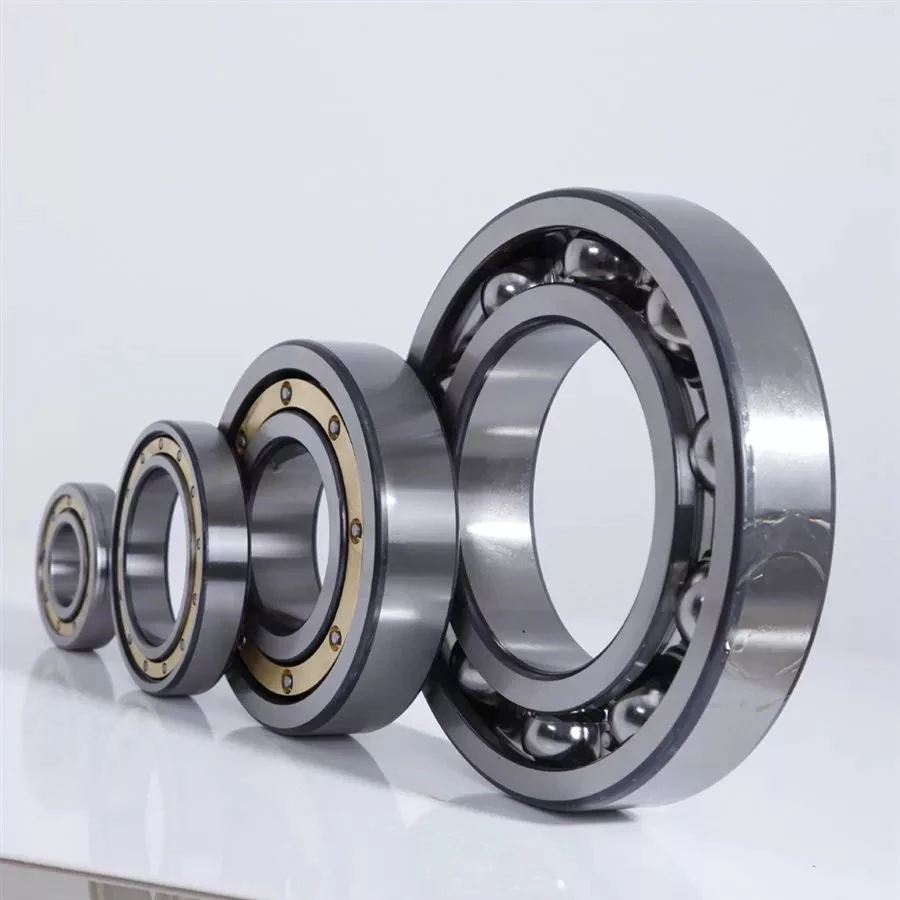
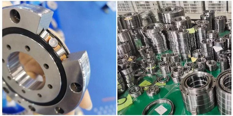
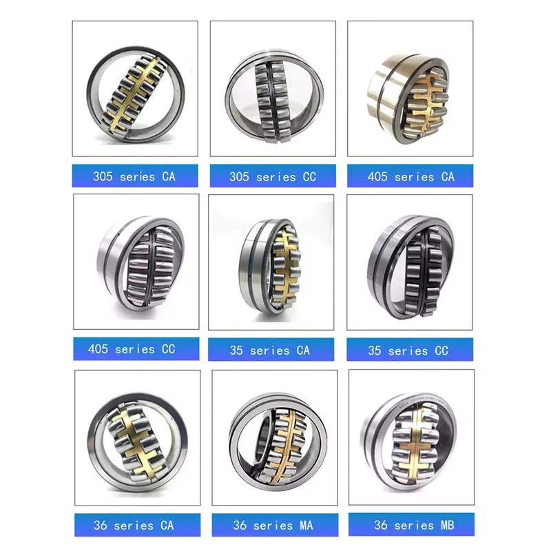
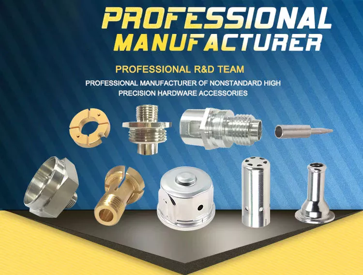
Tag Archives: tractor high quality

China Best Sales OEM Deep Drawn Components Agriculture Tools Farm Tractor Spare Part Suppliers with high quality

Product Description

Product Profile
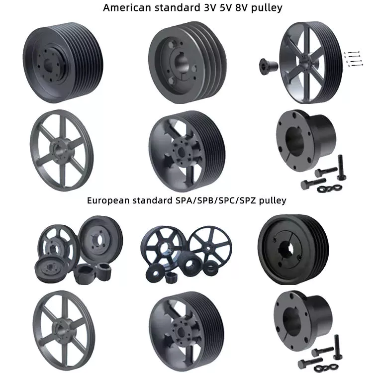
1, We offer custom fabrication service, pls note that the pictures of products are for display only!
 
2,Type: stamping parts for trucks,stamping parts for metal pole,stamping parts for automotive,stamping parts of electrical,etc.
 
3,All products will be newly produced according to clients’ order including samples.Every product will be carefully tested before packing and shipping.
 
4,Certification:ISO 9001:2008,ROHS,CE
 
5,And other details as followings:

Delivery 20-30 working days after receipt of 30% of the deposit
Packaging Standard export package or according to client’s request
Shipping 1.The sample will be shipped by express, like FEDEX, DHL, UPS and EMS.
 And the freight should  be paid by clients. 
2. FOB HangZhou  or HongKong for mass production,
The freight will deal with you for the concrete condition.
Payment 1.T/T , L/C,D/P,D/A
2.High value sample will be charged,Low value sample is free, but the freight should be covered by you. 

 
Surface finish

Aluminum Parts Stainless Steel Parts Steel
Natural/Hard anodize Polishing Blackened
Plating, Brushing, Polishing Plating Zinc /Nickel plating
Powder ,Sandblasting Sandblasting Carburized, Treatment
Laser engraving Laser engraving Chrome plating

 
Our Services

Process extrusion, skiving fin, stamping, die casting, precision CNC machining, drilling, milling, bending, soldering, etc
Service 1.Drawing: we can translate your original drawing, offer best suggestion on design
2.Quality: High quality and Competitive price
3.Inspection: all products must be checked 3 times before packing. 
Values 1.Continuously strive to improve
2.Enjoy our work
3.Treat others the way we wish to be treated with honesty and integrity
4.Disciplined people, Disciplined thinking, Disciplined action

Company Information
we are professional manufacture to produce Sheet Metal Stamping Parts,Spring Clips,Precision Terminal Connectors More than 15 years .
 
  
Equipment & Tools

Inspection Tools CMM, Projection, Calipers, Micro caliper, Thread Micro caliper, Pin gauge, Caliper gauge, Pass meter, etc.
Machining Equipments CNC machines, Automatic lathe machine, Stamping Lathes, Milling/ Grinding machine, Drilling/ Boring/ Honing machine,Ultrasonic cleaning machine,etc.


FAQ
Q1. Are you factory or trading company?    
A: We are a customized factory.
 
Q2.Can you provide sample for us?     
A: Yes, free sample is available
 
Q3. What raw material do you use?   
A: It will recommended by our Project Manager or according to Client’s Request.
 
Q4. How do you ensure quality control? 
A: We inspect every process based on client’s drawings or samples and also check the products before packing.
 
Q5. Is small quantity available?
A: Yes, Small quantity for trial order is available. 
 
Q6. What are your main export countries?
A: America, Australia, Europe, and Southeast Asia, SouthAfrica.
 

Note: For the fast results, when requesting a quote:
  1. Please email or fax us your inquiry with as much information as possible. 
  2. Please include quantities ,material ,thickness, AUTOCAD designs or 3D drawings required.
  3. Quotation will be offered ASAP, via fax or email.

 
Contact
    
Name:Daniel Jing

Why Checking the Drive Shaft is Important

If you hear clicking noises while driving, your driveshaft may need repair. An experienced mechanic can tell if the noise is coming from 1 side or both sides. This problem is usually related to the torque converter. Read on to learn why it’s so important to have your driveshaft inspected by an auto mechanic. Here are some symptoms to look for. Clicking noises can be caused by many different things. You should first check if the noise is coming from the front or the rear of the vehicle.
air-compressor

hollow drive shaft

Hollow driveshafts have many benefits. They are light and reduce the overall weight of the vehicle. The largest manufacturer of these components in the world is CZPT. They also offer lightweight solutions for various applications, such as high-performance axles. CZPT driveshafts are manufactured using state-of-the-art technology. They offer excellent quality at competitive prices.
The inner diameter of the hollow shaft reduces the magnitude of the internal forces, thereby reducing the amount of torque transmitted. Unlike solid shafts, hollow shafts are getting stronger. The material inside the hollow shaft is slightly lighter, which further reduces its weight and overall torque. However, this also increases its drag at high speeds. This means that in many applications hollow driveshafts are not as efficient as solid driveshafts.
A conventional hollow drive shaft consists of a first rod 14 and a second rod 14 on both sides. The first rod is connected with the second rod, and the second rod extends in the rotation direction. The 2 rods are then friction welded to the central area of ​​the hollow shaft. The frictional heat generated during the relative rotation helps to connect the 2 parts. Hollow drive shafts can be used in internal combustion engines and environmentally-friendly vehicles.
The main advantage of a hollow driveshaft is weight reduction. The splines of the hollow drive shaft can be designed to be smaller than the outside diameter of the hollow shaft, which can significantly reduce weight. Hollow shafts are also less likely to jam compared to solid shafts. Hollow driveshafts are expected to eventually occupy the world market for automotive driveshafts. Its advantages include fuel efficiency and greater flexibility compared to solid prop shafts.

Cardan shaft

Cardan shafts are a popular choice in industrial machinery. They are used to transmit power from 1 machine to another and are available in a variety of sizes and shapes. They are available in a variety of materials, including steel, copper, and aluminum. If you plan to install 1 of these shafts, it is important to know the different types of Cardan shafts available. To find the best option, browse the catalog.
Telescopic or “Cardan” prop shafts, also known as U-joints, are ideal for efficient torque transfer between the drive and output system. They are efficient, lightweight, and energy-efficient. They employ advanced methods, including finite element modeling (FEM), to ensure maximum performance, weight, and efficiency. Additionally, the Cardan shaft has an adjustable length for easy repositioning.
Another popular choice for driveshafts is the Cardan shaft, also known as a driveshaft. The purpose of the driveshaft is to transfer torque from the engine to the wheels. They are typically used in high-performance car engines. Some types are made of brass, iron, or steel and have unique surface designs. Cardan shafts are available in inclined and parallel configurations.
Single Cardan shafts are a common replacement for standard Cardan shafts, but if you are looking for dual Cardan shafts for your vehicle, you will want to choose the 1310 series. This type is great for lifted jeeps and requires a CV-compatible transfer case. Some even require axle spacers. The dual Cardan shafts are also designed for lifts, which means it’s a good choice for raising and lowering jeeps.
air-compressor

universal joint

Cardan joints are a good choice for drive shafts when operating at a constant speed. Their design allows a constant angular velocity ratio between the input and output shafts. Depending on the application, the recommended speed limit may vary depending on the operating angle, transmission power, and application. These recommendations must be based on pressure. The maximum permissible speed of the drive shaft is determined by determining the angular acceleration.
Because gimbal joints don’t require grease, they can last a long time but eventually fail. If they are poorly lubricated or dry, they can cause metal-to-metal contact. The same is true for U-joints that do not have oil filling capability. While they have a long lifespan, it can be difficult to spot warning signs that could indicate impending joint failure. To avoid this, check the drive shaft regularly.
U-joints should not exceed 70 percent of their lateral critical velocity. However, if this speed is exceeded, the part will experience unacceptable vibration, reducing its useful life. To determine the best U-joint for your application, please contact your universal joint supplier. Typically, lower speeds do not require balancing. In these cases, you should consider using a larger pitch diameter to reduce axial force.
To minimize the angular velocity and torque of the output shaft, the 2 joints must be in phase. Therefore, the output shaft angular displacement does not completely follow the input shaft. Instead, it will lead or lag. Figure 3 illustrates the angular velocity variation and peak displacement lead of the gimbal. The ratios are shown below. The correct torque for this application is 1360 in-Ibs.

Refurbished drive shaft

Refurbished driveshafts are a good choice for a number of reasons. They are cheaper than brand new alternatives and generally just as reliable. Driveshafts are essential to the function of any car, truck, or bus. These parts are made of hollow metal tubes. While this helps reduce weight and expense, it is vulnerable to external influences. If this happens, it may crack or bend. If the shaft suffers this type of damage, it can cause serious damage to the transmission.
A car’s driveshaft is a critical component that transmits torque from the engine to the wheels. A1 Drive Shaft is a global supplier of automotive driveshafts and related components. Their factory has the capability to refurbish and repair almost any make or model of driveshafts. Refurbished driveshafts are available for every make and model of vehicle. They can be found on the market for a variety of vehicles, including passenger cars, trucks, vans, and SUVs.
Unusual noises indicate that your driveshaft needs to be replaced. Worn U-joints and bushings can cause excessive vibration. These components cause wear on other parts of the drivetrain. If you notice any of these symptoms, please take your vehicle to the AAMCO Bay Area Center for a thorough inspection. If you suspect damage to the driveshaft, don’t wait another minute – it can be very dangerous.
air-compressor

The cost of replacing the drive shaft

The cost of replacing a driveshaft varies, but on average, this repair costs between $200 and $1,500. While this price may vary by vehicle, the cost of parts and labor is generally equal. If you do the repair yourself, you should know how much the parts and labor will cost before you start work. Some parts can be more expensive than others, so it’s a good idea to compare the cost of several locations before deciding where to go.
If you notice any of these symptoms, you should seek a repair shop immediately. If you are still not sure if the driveshaft is damaged, do not drive the car any distance until it is repaired. Symptoms to look for include lack of power, difficulty moving the car, squeaking, clanking, or vibrating when the vehicle is moving.
Parts used in drive shafts include center support bearings, slip joints, and U-joints. The price of the driveshaft varies by vehicle and may vary by model of the same year. Also, different types of driveshafts require different repair methods and are much more expensive. Overall, though, a driveshaft replacement costs between $300 and $1,300. The process may take about an hour, depending on the vehicle model.
Several factors can lead to the need to replace the drive shaft, including bearing corrosion, damaged seals, or other components. In some cases, the U-joint indicates that the drive shaft needs to be replaced. Even if the bearings and u-joints are in good condition, they will eventually break and require the replacement of the drive shaft. However, these parts are not cheap, and if a damaged driveshaft is a symptom of a bigger problem, you should take the time to replace the shaft.

China Best Sales OEM Deep Drawn Components Agriculture Tools Farm Tractor Spare Part Suppliers     with high qualityChina Best Sales OEM Deep Drawn Components Agriculture Tools Farm Tractor Spare Part Suppliers     with high quality

China high quality Peru CZPT Tractor Parts with Hot selling

Product Description

NEW HOLLAND TRACTOR PARTS 

RELATED PRODUCTS

KUBOTA TRACTOR PARTS :M6040,M7040,M9540,L3408,L4508,L3608,L4708

KUBOTA HARVESTER PARTS:PRO688,PRO758,PRO988,DC60,DC68G,DC70,
                                                    DC70PLUS,DC95,DC105

KUBOTA ENGINE PARTS:V2203,V2403,V2603,V3000,V3600,V3800,D1105,D782,D1803

KUBOTA  RICE TRANSPLANTER PARTS:SVP-6CMD,SPV-8CMD,NSPU-68CMD

PACKAING AND SHIPPING

OUR SERVICES

Product: We can provide high quality products with competitive price.

Production Capacity: we have good production capacity and we have enough spare parts stock and
can start to pack at once when you confirm your order.

Online Service: We will reply you at once when we get your enquiry, 24hours online service for you.
Welcome to contact us by email, ,viber,IMO

COMPANY INFORMATION 

Our Company is a professional agricultural machinery spare parts Manufacturer in China,
We specializes in agricultural machinery and accessories, we have a wealth of experience
in parts development, processing, production, so we are well aware of market demand and
can provide good products for our customers.We have been export to many countries such
as Southeast Asia, Australia, American, South America and Africa. We have enough parts
stock and can send out goods soon when customer place order. Dear Friends, it is our
pleasure to know you and look forward to your cooperation.We have a warehouse of 5000 square meters.


How to Choose the Right Worm Shaft

You might be curious to know how to choose the right Worm Shaft. In this article, you will learn about worm modules with the same pitch diameter, Double-thread worm gears, and Self-locking worm drive. Once you have chosen the proper Worm Shaft, you will find it easier to use the equipment in your home. There are many advantages to selecting the right Worm Shaft. Read on to learn more.
worm shaft

Concave shape

The concave shape of a worm’s shaft is an important characteristic for the design of a worm gearing. Worm gearings can be found in a wide range of shapes, and the basic profile parameters are available in professional and firm literature. These parameters are used in geometry calculations, and a selection of the right worm gearing for a particular application can be based on these requirements.
The thread profile of a worm is defined by the tangent to the axis of its main cylinder. The teeth are shaped in a straight line with a slightly concave shape along the sides. It resembles a helical gear, and the profile of the worm itself is straight. This type of gearing is often used when the number of teeth is greater than a certain limit.
The geometry of a worm gear depends on the type and manufacturer. In the earliest days, worms were made similar to simple screw threads, and could be chased on a lathe. During this time, the worm was often made with straight-sided tools to produce threads in the acme plane. Later, grinding techniques improved the thread finish and reduced distortions resulting from hardening.
When a worm gearing has multiple teeth, the pitch angle is a key parameter. A greater pitch angle increases efficiency. If you want to increase the pitch angle without increasing the number of teeth, you can replace a worm pair with a different number of thread starts. The helix angle must increase while the center distance remains constant. A higher pitch angle, however, is almost never used for power transmissions.
The minimum number of gear teeth depends on the angle of pressure at zero gearing correction. The diameter of the worm is d1, and is based on a known module value, mx or mn. Generally, larger values of m are assigned to larger modules. And a smaller number of teeth is called a low pitch angle. In case of a low pitch angle, spiral gearing is used. The pitch angle of the worm gear is smaller than 10 degrees.
worm shaft

Multiple-thread worms

Multi-thread worms can be divided into sets of one, two, or 4 threads. The ratio is determined by the number of threads on each set and the number of teeth on the apparatus. The most common worm thread counts are 1,2,4, and 6. To find out how many threads you have, count the start and end of each thread and divide by two. Using this method, you will get the correct thread count every time.
The tangent plane of a worm’s pitch profile changes as the worm moves lengthwise along the thread. The lead angle is greatest at the throat, and decreases on both sides. The curvature radius r” varies proportionally with the worm’s radius, or pitch angle at the considered point. Hence, the worm leads angle, r, is increased with decreased inclination and decreases with increasing inclination.
Multi-thread worms are characterized by a constant leverage between the gear surface and the worm threads. The ratio of worm-tooth surfaces to the worm’s length varies, which enables the wormgear to be adjusted in the same direction. To optimize the gear contact between the worm and gear, the tangent relationship between the 2 surfaces is optimal.
The efficiency of worm gear drives is largely dependent on the helix angle of the worm. Multiple thread worms can improve the efficiency of the worm gear drive by as much as 25 to 50% compared to single-thread worms. Worm gears are made of bronze, which reduces friction and heat on the worm’s teeth. A specialized machine can cut the worm gears for maximum efficiency.

Double-thread worm gears

In many different applications, worm gears are used to drive a worm wheel. These gears are unique in that the worm cannot be reversed by the power applied to the worm wheel. Because of their self-locking properties, they can be used to prevent reversing motion, although this is not a dependable function. Applications for worm gears include hoisting equipment, elevators, chain blocks, fishing reels, and automotive power steering. Because of their compact size, these gears are often used in applications with limited space.
Worm sets typically exhibit more wear than other types of gears, and this means that they require more limited contact patterns in new parts. Worm wheel teeth are concave, making it difficult to measure tooth thickness with pins, balls, and gear tooth calipers. To measure tooth thickness, however, you can measure backlash, a measurement of the spacing between teeth in a gear. Backlash can vary from 1 worm gear to another, so it is important to check the backlash at several points. If the backlash is different in 2 places, this indicates that the teeth may have different spacing.
Single-thread worm gears provide high speed reduction but lower efficiency. A multi-thread worm gear can provide high efficiency and high speed, but this comes with a trade-off in terms of horsepower. However, there are many other applications for worm gears. In addition to heavy-duty applications, they are often used in light-duty gearboxes for a variety of functions. When used in conjunction with double-thread worms, they allow for a substantial speed reduction in 1 step.
Stainless-steel worm gears can be used in damp environments. The worm gear is not susceptible to rust and is ideal for wet and damp environments. The worm wheel’s smooth surfaces make cleaning them easy. However, they do require lubricants. The most common lubricant for worm gears is mineral oil. This lubricant is designed to protect the worm drive.
worm shaft

Self-locking worm drive

A self-locking worm drive prevents the platform from moving backward when the motor stops. A dynamic self-locking worm drive is also possible but does not include a holding brake. This type of self-locking worm drive is not susceptible to vibrations, but may rattle if released. In addition, it may require an additional brake to keep the platform from moving. A positive brake may be necessary for safety.
A self-locking worm drive does not allow for the interchangeability of the driven and driving gears. This is unlike spur gear trains that allow both to interchange positions. In a self-locking worm drive, the driving gear is always engaged and the driven gear remains stationary. The drive mechanism locks automatically when the worm is operated in the wrong manner. Several sources of information on self-locking worm gears include the Machinery’s Handbook.
A self-locking worm drive is not difficult to build and has a great mechanical advantage. In fact, the output of a self-locking worm drive cannot be backdriven by the input shaft. DIYers can build a self-locking worm drive by modifying threaded rods and off-the-shelf gears. However, it is easier to make a ratchet and pawl mechanism, and is significantly less expensive. However, it is important to understand that you can only drive 1 worm at a time.
Another advantage of a self-locking worm drive is the fact that it is not possible to interchange the input and output shafts. This is a major benefit of using such a mechanism, as you can achieve high gear reduction without increasing the size of the gear box. If you’re thinking about buying a self-locking worm gear for a specific application, consider the following tips to make the right choice.
An enveloping worm gear set is best for applications requiring high accuracy and efficiency, and minimum backlash. Its teeth are shaped differently, and the worm’s threads are modified to increase surface contact. They are more expensive to manufacture than their single-start counterparts, but this type is best for applications where accuracy is crucial. The worm drive is also a great option for heavy trucks because of their large size and high-torque capacity.

China high quality Peru CZPT Tractor Parts     with Hot sellingChina high quality Peru CZPT Tractor Parts     with Hot selling

China high quality Customized Steel Stamping Metal Fabrication Trailer Truck Tractor Parts near me supplier

Product Description

Customized steel stamping metal fabrication trailer truck tractor parts

Production information 
 

Model NO. Customized  Tolerances  0.01mm
Product name metal stamping parts  Finish  Powder coating, anodizing, paint, zinc plated and etc 
Color  As per customers’ requirements  Trade mark  Merid 
Package  Wooden case, paper carton, pallet, iron case  Market USA, UK, German, Japan, Netherlands, Australia, Mexico, Sweden, and so on.
Origin  Made in China  Production lead time  7-30 days.


Description
Material range Carbon steel, iron, alloy steel , stainless steel, aluminum alloy; brass, copper, bronze, copper alloy ect.
Surface  Powder coating, paint, hot dip galvanized, electro galvanized, chrome plated, nickel plated, polishing etc.


Process

Metal fabrication, machining, welding, forming, shaping, drilling, stamping, laser cutting, CNC lathe, CNC milling, spot welding, full welding, tig welding, mig welding, riveting, tapping, grinding, assembling, etc.

Machinery  15-500ton stamping machine, CNC lathe, CNC milling, band saw cutter, auto welding robot, butt welding machine, beding machine, plate cutting machine, shot blasting machine, drilling machine, polishing machine, flame cutting machine.
Our capacities  stamping, welding, maching, casting, forging, assembly, surface treatment, deep drawing etc.
Service  OEM&ODM
Material thickness  0.5mm ~12mm, or as per customers’ requirements.
Application range  Construction, agricultural, automotive, electric, sports accessories, furniture, household appliance etc.

Our products

Company Profile 
 

HangZhou CZPT Machinery Co.,Ltd is an ISO certified custom metal parts manufacturer, established in 1991, providing custom metals parts in Stamping, Casting, Machining and Welding for a variety of industries and applications, including Medical, Automotive, Agricultural, Farming, Architectural and other industries.


Merid offers comprehensive in-house services, from initial design to fabrication. For over 27 years, CZPT has established a good reputation for meeting customers’ requirements and quality standards as a custom parts manufacturer.


Our strong team is dedicated to providing you the world-class quality and service, our team includes professional engineers and designers, skilled tool makers, experienced QC inspectors, well-trained machinists and management personnel.

Package 

QC equipments 

Our Exhibition

Why choose us? 

1)  We have our own factory, quality can be controlled seriously and price is very competitive.

2) We have been manufacturing metal stamping parts for nearly 30 years..

3) We have professional testing equipments and quality control personnel.

4) We have own R&D department experienced technicians.

5) On timely delivery and 24/7 service.

FAQ

Q1: Are you a trading company or a manufacturer?
We are manufacturer, established in 1991 with trade team for international service.
 
Q2: How long is your delivery time?
Normally, the production lead time for sample is 10-15 days and lead time for the mass production order is about 30 days as per quantity.
Q3: How long will it take for quotation?
Within 1 working day if drawings are available.
 
Q4: Do you offer samples?
Yes, samples can be provided to check and test.
 
Q5: Which countries are your main markets?
America, Canada, Mexico, Europe, Australia,German, Netherlands and so on.
 
Q6: Do you have experience of doing business with overseas customers?
Yes, we have over 10 years exporting experience and most of our products are exported to overseas market. We specialized in the high quality custom metal parts. 


The Functions of Splined Shaft Bearings

Splined shafts are the most common types of bearings for machine tools. They are made of a wide variety of materials, including metals and non-metals such as Delrin and nylon. They are often fabricated to reduce deflection. The tooth profile will become deformed with time, as the shaft is used over a long period of time. Splined shafts are available in a huge range of materials and lengths.

Functions

Splined shafts are used in a variety of applications and industries. They are an effective anti-rotational device, as well as a reliable means of transmitting torque. Other types of shafts are available, including key shafts, but splines are the most convenient for transmitting torque. The following article discusses the functions of splines and why they are a superior choice. Listed below are a few examples of applications and industries in which splines are used.
Splined shafts can be of several styles, depending on the application and mechanical system in question. The differences between splined shaft styles include the design of teeth, overall strength, transfer of rotational concentricity, sliding ability, and misalignment tolerance. Listed below are a few examples of splines, as well as some of their benefits. The difference between these styles is not mutually exclusive; instead, each style has a distinct set of pros and cons.
A splined shaft is a cylindrical shaft with teeth or ridges that correspond to a specific angular position. This allows a shaft to transfer torque while maintaining angular correspondence between tracks. A splined shaft is defined as a cylindrical member with several grooves cut into its circumference. These grooves are equally spaced around the shaft and form a series of projecting keys. These features give the shaft a rounded appearance and allow it to fit perfectly into a grooved cylindrical member.
While the most common applications of splines are for shortening or extending shafts, they can also be used to secure mechanical assemblies. An “involute spline” spline has a groove that is wider than its counterparts. The result is that a splined shaft will resist separation during operation. They are an ideal choice for applications where deflection is an issue.
A spline shaft’s radial torsion load distribution is equally distributed, unless a bevel gear is used. The radial torsion load is evenly distributed and will not exert significant load concentration. If the spline couplings are not aligned correctly, the spline connection can fail quickly, causing significant fretting fatigue and wear. A couple of papers discuss this issue in more detail.
splineshaft

Types

There are many different types of splined shafts. Each type features an evenly spaced helix of grooves on its outer surface. These grooves are either parallel or involute. Their shape allows them to be paired with gears and interchange rotary and linear motion. Splines are often cold-rolled or cut. The latter has increased strength compared to cut spines. These types of shafts are commonly used in applications requiring high strength, accuracy, and smoothness.
Another difference between internal and external splined shafts lies in the manufacturing process. The former is made of wood, while the latter is made of steel or a metal alloy. The process of manufacturing splined shafts involves cutting furrows into the surface of the material. Both processes are expensive and require expert skill. The main advantage of splined shafts is their adaptability to a wide range of applications.
In general, splined shafts are used in machinery where the rotation is transferred to an internal splined member. This member can be a gear or some other rotary device. These types of shafts are often packaged together as a hub assembly. Cleaning and lubricating are essential to the life of these components. If you’re using them on a daily basis, you’ll want to make sure to regularly inspect them.
Crowned splines are usually involute. The teeth of these splines form a spiral pattern. They are used for smaller diameter shafts because they add strength. Involute splines are also used on instrument drives and valve shafts. Serration standards are found in the SAE. Both kinds of splines can also contain a ball bearing for high torque. The difference between the 2 types of splines is the number of teeth on the shaft.
Internal splines have many advantages over external ones. For example, an internal spline shaft can be made using a grinding wheel instead of a CNC machine. It also uses a more accurate and economical process. Furthermore, it allows for a shorter manufacturing cycle, which is essential when splining high-speed machines. In addition, it stabilizes the relative phase between the spline and thread.
splineshaft

Manufacturing methods

There are several methods used to fabricate a splined shaft. Key and splined shafts are constructed from 2 separate parts that are shaped in a synchronized manner to transfer torque uniformly. Hot rolling is 1 method, while cold rolling utilizes low temperatures to form metal. Both methods enhance mechanical properties, surface finishes, and precision. The advantage of cold rolling is its cost-effectiveness.
Cold forming is 1 method, as well as machining and assembling. Cold forming is a unique process that allows the spline to be shaped to the desired shape. The resulting shape provides maximum contact area and torsional strength. Standard splines are available in standard sizes, but custom lengths can also be ordered. CZPT offers various auxiliary equipment, such as mating sleeves and flanged bushings.
Cold forging is another method. This method produces long splined shafts that are used in automobile propellers. After the spline portion is cut out, it is worked on in a hobbing machine. Work hardening enhances the root strength of the splined portion. It can be used for bearings, gears, and other mechanical components. Listed below are the manufacturing methods for splined shafts.
Parallel splines are the simplest of the splined shaft manufacturing methods. Parallel splines are usually welded to shafts, while involute splines are made of metal or non-metals. Splines are available in a wide variety of lengths and materials. The process is usually accompanied by a process called milling. The workpiece rotates to produce the serrated surface.
Splines are internal or external grooves in a splined shaft. They work in combination with keyways to transfer torque. Male and female splines are used in gears. Female and male splines correspond to 1 another to ensure proper angular correspondence. Involute splines have more surface area and thus are stronger than external splines. Moreover, they help the shaft fit into a grooved cylindrical member without misalignment.
A variety of other methods of manufacturing a splined shaft can be used to produce a splined shaft. Spline shafts can be produced using broaching and shaping, 2 precision machining methods. Broaching uses a metal tool with successively larger teeth to remove metal and create ridges and holes in the surface of a material. However, this process is expensive and requires special expertise.
splineshaft

Applications

The splined shaft is a mechanical component with a helix-like shape formed by the equal spacing of grooves in a circular ring. The splines can either have parallel or involute sides. The splines minimize stress concentration in stationary joints and can be used in both rotary and linear motion. In some cases, splines are rolled rather than cut. The latter is more durable than cut splines and is often used in applications requiring high strength, accuracy, and smooth finish.
Splined shafts are commonly made of carbon steel. This alloy steel has a low carbon content, making it easy to work with. Carbon steel is a great choice for splines because it is malleable. Generally, high-quality carbon steel provides a consistent motion. Steel alloys are also available that contain nickel, chromium, copper, and other metals. If you’re unsure of the right material for your application, you can consult a spline chart.
Splines are a versatile mechanical component. They are easy to cut and fit. Splines can be internal or external, with teeth positioned at equal intervals on both sides of the shaft. This allows the shaft to engage with the hub around the entire circumference of the hub. It also increases load capacity by creating a constant multiple-tooth point of contact with the hub. For this reason, they’re used extensively in rotary and linear motion.
Splined shafts are used in a wide variety of industries. CZPT Inc. offers custom and standard splined shafts for a variety of applications. When choosing a splined shaft for a specific application, consider the surrounding mated components, torque requirements, and size requirements. These 3 factors will make it the ideal choice for your rotary equipment. And you’ll be pleased with the end result!
There are many types of splines and their applications are endless. They transfer torque and angular misalignment between parts, and they also enable the axial rotation of assembled components. Therefore, splines are an essential component of machinery and are used in a wide range of applications. This type of shaft can be found in various types of machines, from household appliances to industrial machinery. So, the next time you’re looking for a splined shaft, make sure you look for a splined one.

China high quality Customized Steel Stamping Metal Fabrication Trailer Truck Tractor Parts     near me supplier China high quality Customized Steel Stamping Metal Fabrication Trailer Truck Tractor Parts     near me supplier

China Custom High Quality Tractor Sheet Metal Parts with Free Design Custom

Product Description

our product is service!
We  provide a service to manufacture your products.Speaking with you on an individual basis allows us 
the ability to support your design and development,ensuring product produce ability.

Stamping: 
 1.Metal stamping, cold stamping,hot stamping 
 2.OEM,can be customized 
 3.Alloy, Aluminum,Brass,steel ,copper,stainless steel,mild steel,carbon steel.
 4.Durable
 5.Tolerance Control: from +,-0.003MM 
 6.After-sales-service: take 100% responsibility for any quaulity issues!
 
Our Advantage:
1.Good Quality
 2.Competitive Price
 3.Long production history
 4. International Quality Certified
 5.Skilled workers
 6.Prompt Delivery Time
 7.Warranty After-sales-service
 

PRODUCT DESCRIPTION:
We provide high standard manufacturing directly services for CNC machining/ forging / casting / stamping /metal fabrication…
(Stamping including: Progressive die stamping, mold stamping,hot stamping, cold stamping ,deep drawn…)
Material

Stainless Steel SS201,SS301, SS303, SS304, SS316, SS316L,SS416 ,AISI 440C,17-4PH etc.
Steel/Alloy mild steel, Carbon steel, 4140, 4340,65Mn,60Si2Mn, Q235, Q345B, 1571steel, 1045steel,A106,A105, A570-50,CR-MO4130,Astm A487 grade 9A, 52100 Bearing steel ,S45c, Sm490A, AVP/S235JRG2,DD14, 1.0037 ,etc, ASTM 1197-47, 25CRMO4V,SCM435, 11SMNPB30,1. 0571 ,.A36
Brass HPb63, HPb62, HPb61, HPb59, H59, H62, H68, H80 ,Bronze 660, C93200,Bronze CDA873 or 956,CDA873,C95600,MAILEABLE IRON ASTM A47-77, etc.
Copper C11000,C12000,C12000 C36000,C100 etc.
Aluminum AL1100,AL6061, Al6063-T6, AL6082, AL7075, AL5052, A380 etc.
Iron 1213, 12L14, 1215,ductile iron astm a536, 60-40-18, 60-45-12, FE E420,etc
Plastic ABS, PC, PE, POM, Delrin 2700 NC571, Nylon, Teflon, PP,PEI, Peek etc.

Finishing:

Zinc plating, Chrome plating, Nickel plating, Tin plating, Polishing, Anodizing, Power-coating, Dacromet, Oxide black, Sandblast Anodizing, Electroless nickel, Fe/Zn8/C PER ISO 2081, etc.
Specifications:
Design: We use the most advanced CZPT design software Auto CAD, Pro/E, Solidworks, UG (dwg, dxf, IGS, STP, X-T)
Manufacture: We use advanced technology, unmatched skill, professional and advanced equipment size range from 15T-10000T, and experienced technicians to fit our customers requirements, like tooling manufacturing,robot welding,forging, steel casting, stamping and surface treatment service
Process and Capability: Cnc machining, Casting,Forging,Progression die, Stamping, Metal Deep drawn, Bending, Punching, Threading, Welding, Tapping, Riveting, Grinding, Laser cutting,Metal Fabrication,forming,spinning, CNC Punching, Plasma cutting, Goffered, Stretch forming ,Tig/Mig Welding,Assembling, Shearing, Blanking, CNC Bending…………,
Price Terms: Fob HangZhou or ZheJiang or any other port in CHINA
Lead time: 20-50days based on the different products
Packaging: Wooden package and canton case or as per customers’ requirement
Certification: ISO9001:2018 , SGS , TS16949,API 8C
Industry: these parts are used in hydraulic presses, press line automation and die handling equipment,Automotive, Electrical, Building, Furniture, Machine assembly, Computer, Air industry , Oil field Equipments, Marine equipments, Mine equipment,Agricultural Machines,Transportation Equipments, OEM/ODM Electronics……
 

DETAILED PHOTOS
OUR ADVANTAGES:
1.Good Quality with strict inspection process. control the tolerance up to +,-0.002MM.
2.Competitive Price and prompt delivery time.
3. International Quality Certified
4.Skilled workers
5.Warranty After-sales-service
6. Prompt delivery time.

FAQ:
Q1: How can I get quote ?
A1: pls send us PDF,JPG,or other 2D files and 3D drawings. if you don;t have drawings. pls send me samples.

Q2: How you guarantee the quality?
A2: Our production will be strictly comply with the drawing requirements.we offer details photos and inspected reports to let you confirm before shipment.we will take the responsibilty for any quality issue.

Q3: What is payment term?
A3: 30% depoist in advance and the balance to be paid against the copy of BL.or LC at sight.

Q4: How about the shipment and package?
A4: If you have nominated forwarding company, we can contact him, if you don’t have .my company will organise the best-service forwarding company with the lowest shipping cost.

Q5: How to pack the cargos?
A5: If you have special packing request, pls send us design, my company will make the package exactly according to your designs.
or my company use our own good and standard package (carton or wooden box, or pallet or others according


How to Replace a Bearing

If you want to select a bearing for a specific application, you should know a few basics. This article will give you an overview of ball, angular contact, and sliding-contact bearings. You can choose a bearing according to the application based on the characteristics of its material and preload. If you are not sure how to choose a bearing, try experimenting with it. The next step is to understand the Z-axis, which is the axes along which the bearing moves.

Z axis

When it comes to replacing your Z axis bearing, there are several things you must know. First, you need to make sure that the bearings are seated correctly. Then, you should check the tension and rotation of each one. To ensure that both bearings are equally tensioned, you should flex the Core to the desired angle. This will keep the Z axis perpendicular to the work surface. To do this, first remove the Z axis bearing from its housing and insert it into the Z axis motor plate. Next, insert the flanged bearing into the Z axis motor plate and secure it with 2 M5x8mm button head cap screws.
Make sure that the bearing plate and the Z Coupler part are flush and have equal spacing. The spacing between the 2 parts is important, as too much spacing will cause the leadscrew to become tight. The screws should be very loose, with the exception of the ones that engage the nylocks. After installing the bearing, the next step is to start the Z axis. Once this is done, you’ll be able to move it around with a stepper.

Angular contact

bearing
Ball bearings are made with angular contacts that result in an angle between the bearing’s races. While the axial load moves in 1 direction through the bearing, the radial load follows a curved path, tending to separate the races axially. In order to minimize this frictional effect, angular contact bearings are designed with the same contact angle on the inner and outer races. The contact angle must be chosen to match the relative proportions of the axial and radial loads. Generally, a larger contact angle supports a higher axial load, while reducing radial load.
Ball bearings are the most common type of angular contact bearings. Angular contact ball bearings are used in many applications, but their primary purpose is in the spindle of a machine tool. These bearings are suitable for high-speed, precision rotation. Their radial load capacity is proportional to the angular contact angle, so larger contact angles tend to enlarge with speed. Angular contact ball bearings are available in single and double-row configurations.
Angular contact ball bearings are a great choice for applications that involve axial loads and complex shapes. These bearings have raceways on the inner and outer rings and mutual displacement along the axial axis. Their axial load bearing capacity increases as the contact Angle a rises. Angular contact ball bearings can withstand loads up to 5 times their initial weight! For those who are new to bearings, there are many resources online dedicated to the subject.
Despite their complexity, angular contact ball bearings are highly versatile and can be used in a wide range of applications. Their angular contact enables them to withstand moderate radial and thrust loads. Unlike some other bearings, angular contact ball bearings can be positioned in tandem to reduce friction. They also feature a preload mechanism that removes excess play while the bearing is in use.
Angular contact ball bearings are made with different lubricants and cage materials. Standard cages for angular contact ball bearings correspond to Table 1. Some are machined synthetic resins while others are molded polyamide. These cage materials are used to further enhance the bearing’s axial load capacity. Further, angular contact ball bearings can withstand high speeds and radial loads. Compared to radial contact ball bearings, angular contact ball bearings offer the greatest flexibility.

Ball bearings

bearing
Ball bearings are circular structures with 2 separate rings. The smaller ring is mounted on a shaft. The inner ring has a groove on the outer diameter that acts as a path for the balls. Both the inner and outer ring surfaces are finished with very high precision and tolerance. The outer ring is the circular structure with the rolling elements. These elements can take many forms. The inner and outer races are generally made of steel or ceramic.
Silicon nitride ceramic balls have good corrosion resistance and lightweight, but are more expensive than aluminum oxide balls. They also exhibit an insulating effect and are self-lubricating. Silicon nitride is also suitable for high-temperature environments. However, this type of material has the disadvantage of wearing out rapidly and is prone to cracking and shattering, as is the case with bearing steel and glass. It’s also less resistant to heat than aluminum oxide, so it’s best to buy aluminum nitride or ceramic ball bearings for applications that are subjected to extremely high temperatures.
Another type of ball bearings is the thrust bearing. It has a special design that accommodates forces in both axial and radial directions. It is also called a bidirectional bearing because its races are side-by-side. Axial ball bearings use a side-by-side design, and axial balls are used when the loads are transmitted through the wheel. However, they have poor axial support and are prone to separating during heavy radial loads.
The basic idea behind ball bearings is to reduce friction. By reducing friction, you’ll be able to transfer more energy, have less erosion, and improve the life of your machine. With today’s advances in technology, ball bearings can perform better than ever before. From iron to steel to plastics, the materials used in bearings have improved dramatically. Bearings may also incorporate an electromagnetic field. So, it’s best to select the right 1 for your machine.
The life expectancy of ball bearings depends on many factors, including the operating speed, lubrication, and temperature. A single million-rpm ball bearing can handle between 1 and 5 million rotations. As long as its surface contact area is as small as possible, it’s likely to be serviceable for at least 1 million rotations. However, the average lifespan of ball bearings depends on the application and operating conditions. Fortunately, most bearings can handle a million or more rotations before they start showing signs of fatigue.

Sliding-contact bearings

bearing
The basic principle behind sliding-contact bearings is that 2 surfaces move in contact with 1 another. This type of bearing works best in situations where the surfaces are made of dissimilar materials. For instance, a steel shaft shouldn’t run in a bronze-lined bore, or vice versa. Instead, 1 element should be harder than the other, since wear would concentrate in that area. In addition, abrasive particles tend to force themselves into the softer surface, causing a groove to wear in that part.
Sliding-contact bearings have low coefficients of friction and are commonly used in low-speed applications. Unlike ball and roller bearings, sliding contact bearings have to be lubricated on both sides of the contacting surfaces to minimize wear and tear. Sliding-contact bearings generally are made of ceramics, brass, and polymers. Because of their lower friction, they are less accurate than rolling-element bearings.
Sliding-contact bearings are also known as plain or sleeve bearings. They have a sliding motion between their 2 surfaces, which is reduced by lubrication. This type of bearing is often used in rotary applications and as guide mechanisms. In addition to providing sliding action, sliding-contact bearings are self-lubricating and have high load-carrying capacities. They are typically available in 2 different types: plain bearings and thrust bearings.
Sliding-contact linear bearing systems consist of a moving structure (called the carriage or slide) and the surfaces on which the 2 elements slide. The surfaces on which the bearing and journal move are called rails, ways, or guides. A bore hole is a complex geometry, and a minimum oil film thickness h0 is usually used at the line of centers. It is possible to have a sliding-contact bearing in a pillow block.
Because these bearings are porous, they can absorb 15 to 30% of the lubrication oil. This material is commonly used in automobile and machine tools. Many non-metallic materials are used as bearings. One example is rubber, which offers excellent shock absorbency and embeddability. While rubber has poor strength and thermal conductivity, it is commonly used in deep-well pumps and centrifugal pumps. This material has high impact strength, but is not as rigid as steel.

China Custom High Quality Tractor Sheet Metal Parts     with Free Design CustomChina Custom High Quality Tractor Sheet Metal Parts     with Free Design Custom

China supplier Price of Cheap CZPT Tractor Rotary Tiller Blade Spare Parts in Peru with high quality

Product Description

Price Of Cheap CZPT Tractor Rotary Tiller Blade Spare Parts In Peru

Detailed description: 
1) Material: 65Mn, 60Si2Mn, 28MnSiB
2) Produding: forging/heat treatment/painting
3) Painting: black, blue, red or as your requirement
4) Packaging: carton packing or according to your request for packing 
5) All kinds of blade types, such as 581,681,GN12–1 hole, 2 hole, K19,216,and so on
6) Competitive price, long using life, fast and prompt delivery, best after-sales service.

We offer OEM and ODM order, if you have any special requirements, please kindly inform us, our engineering department will study and offer you the suitable solution, we will do our best to meet various requirements of clients.

COMPANY INTRODUCTION

HangZhou CZPT Co., Ltd is a vibrant company, mainly engaged agricultural machinery production and trading. Our business contains: Sales of all kinds of farming machines and related spare parts, specially professionally in full feeding crawler combine harvester, rice transplanter, power tiller, and also spare parts of brand farming machines such as Kubota, Yanmar, World, Mubota, Xingguang. Major market covers South East Asia, Middle East, as well as South America. Both rich experience of exporting and excellent before and after sales service, bring us a very goods reputation.

FAQs

1.Q: How long is your delivery time?
A: Normally, it takes 15-20days to delivery after your deposit receipt or L/C at sight

2.How many spare parts can be loaded in 1 container?
1)20 Feet Container loads:40000pieces 
2)Sample or LCL shipment are also welcome

3.Q: What is the payment term?
A: Irrevocable L/C at sight or 30% T/T in advance and balance against B/L copy.
 

Advantages and disadvantages of different types of bushings

Bushings are a simple but essential part of machinery with sliding or rotating shaft assemblies. This type of bearing is used in a wide variety of industries because its high load-carrying capacity and excellent anti-friction properties make it a necessity for construction, mining, hydropower, transportation and agricultural machinery. In addition to these applications, bushings also play a vital role in material handling and food processing. This article explores the various types of bushings available.
bushing

air casing

The air bushing forms a frictionless cylinder that applies the load to the rotating object. Bushings are used to measure torque and provide self-centering force in applications where linear motion is critical. The following are load equations that can be used to select the appropriate air sleeve for your application. To learn more about these air sleeves, read on. This article discusses the benefits and uses of air bushings in linear motion.
Bushings have many advantages over bearings. They are not prone to wear and corrosion. Unlike bearings, they can easily bypass conversion and inspection periods. Their high-quality design guarantees reliable machine performance, yet they are inexpensive and easy to replace. In many industries, air compressors are essential for sports. The air bushing eliminates friction, allowing the compressor to work more efficiently. They can also help eliminate the need for frictionless bearings and improve the overall efficiency of the machine.
Another type of air bearing is the cylindrical bushing. These are used for linear and aerostatic motion. Their low friction properties allow them to support radial loads without wearing out or damaging components. They are usually used for normal sized shafts. Air bushings have several components that can be used with other types of air bearings. Cylindrical air bearings have 4 o-ring grooves that allow them to be inserted into the structure. They are often used with other types of air bearings for smoother motion.

rubber bushing

If you’re looking to buy a new suspension system, you may be wondering if rubber or polyurethane is the right choice. Rubber is less expensive, but not without its drawbacks. Polyurethane is more durable and offers better handling and suspension. Rubber bushings also reduce road feel, while polyurethane isolates the driver from the road. Both materials will help you improve handling and alignment, but each has advantages and disadvantages.
Typically, rubber bushings are cylindrical components with metal inner and outer surfaces. These metals can be stainless steel, mild steel or aluminum. They are usually stress relieved and prestressed for maximum durability. They are designed to meet the exact specifications of a specific application. For example, shock-absorbing rubber bushings are cushioning pads made of polyurethane that absorb road bumps and noise.
Unlike polyurethane, rubber suspension bushings have a shorter lifespan than polyurethane. This is because rubber is more susceptible to damage from UV rays, road chemicals and oils. The rubber also stretches and warps due to the pressure of the road. The rubber bushing also squeaks, which can be cause for concern. But if the noise persists for a long time, it may be a sign that your vehicle needs a new suspension system.
The main reason why cars use rubber bushings is for shock absorption. During machine use, vibration and noise caused by the movement of parts can cause serious damage. To prevent this, rubber bushings act as shock absorbers and damping agents. Rubber bushings are an excellent choice for automakers, but they are also used in a variety of industrial settings.
bushing

Polyurethane bushing

If you want to make your vehicle handle better, polyurethane bushings may be the answer. They come in different shapes and sizes and can improve a wide range of areas. This article will explore the advantages and disadvantages of polyurethane bushings and their potential place in your car. However, before you decide to upgrade your suspension, you should understand the various advantages and disadvantages of polyurethane bushings.
The main difference between a polyurethane bushing and a rubber bushing is how the bushing rides on the suspension arm. Polyurethane bushings do not have faces that slide against each other like rubber bushings. This means they allow for more rotation and flexion, as well as consistent alignment of the control arms. Polyurethane bushings require lubrication, but only need to be lubricated every 5 years, much longer than equivalent rubber bushings.
Another difference between polyurethane and rubber bushings is hardness. The former has the least elasticity and is generally the most suitable for street use. While rubber bushings provide the best NVH quality, they are also notorious for changing suspension geometry. Rubber is known to be an excellent choice for street use, but polyurethane has a lifespan that far outlasts rubber.

bronze bushing

There are 2 main types of bronze bushings, sintered and cast. The latter require additional lubrication and are typically used in applications where powder metal products cannot be secured. The former is cheaper than the latter, but the process is more expensive. Bronze bushings can be used in environments where the material will be exposed to high temperature and vibration. For these reasons, the production process is relatively slow and expensive.
The strength of bronze is the main reason why they are so popular. Brass is a softer metal that deforms and corrodes easily. The bronze casing can withstand continuous immersion in water and can last for hundreds of years with little or no maintenance. However, it is important to note that this metal is not resistant to aggressive chemicals and requires regular maintenance to keep it in good condition.
Bronze bushings offer many advantages, including durability and aesthetics. Bronze bushings are available in a variety of sizes and can be ordered in imperial and metric sizes. They can be built to your specifications and are very durable. You can even custom order them if you want. And because they can be customized, they are an excellent choice for high-end applications. The quality of the bronze bushings is second to none.

Plastic bushing

Engineered composite plastic bushings have been shown to last longer than bronze bushings and have also been found to reduce maintenance costs by up to 40%. Plastic bushings have become the first choice for thousands of applications, including medical equipment, food processing machinery, pumps, and more. Bronze bushings are oil-impregnated, but their performance is limited by their inherent weaknesses: oil-impregnated bronze tends to develop high levels of capillary action and requires rotational motion to maintain an intact oil film. Low speed and intermittent use of bronze bushings can also hinder the ability of the lubricant to provide adequate lubrication.
Advantages of plastic bushings over metal include low friction, non-reactive surfaces, and long life. CZPT offers a variety of engineering plastics that outperform traditional metals in a range of applications. For example, nylon bushings resist wear while requiring little lubrication. In addition, polymer-shaped plastics are lightweight and highly resistant to aggressive cleaning agents and chemicals.
Besides being less expensive than metal bushings, plastic bushings offer many other advantages. They are very durable, have a low coefficient of friction, and are more wear-resistant than metal. Unlike metal, plastic bushings do not require lubrication and do not absorb dust and oil like metal bushings. They are lightweight, easy to maintain and last longer. This makes them an excellent choice for many applications.
bushing

Sleeve bearing

Sleeve bearings are simple pipes with matching components. They facilitate linear motion by absorbing friction and vibration. They can withstand heavy loads and work at high temperatures for long periods of time. Flange bearings are similar to sleeve bearings, but are enclosed and rotated in a housing unit. Sleeve bearings have higher load-carrying capacity and resistance to shock loads. Furthermore, they are lightweight and low cost.
Another name for sleeve bearings is babbitt radial bearings. These bearings are usually made of bronze and have straight inner and outer diameters. They are also impregnated with oil and can withstand radial loads. Typical uses for sleeve bearings are agriculture, automotive and machine tools. Sleeves can also be solid or cored material, depending on the intended use.
The type of sleeve bearing used in the bushing is important in determining which type of bushing to buy. Sleeve bearings are sized based on pressure and speed considerations. Typically, the PV limit is an upper bound on the combined pressure and velocity for a given casing material. In some cases, the sleeve bearing used in the bushing is the same as the plain bearing.
Sleeve bearings are simple in design and made from a variety of materials, including bronze and plastic. They are more affordable than metal, but plastic is still not inaudible. Plastic sleeve bearings will rattle like metal bearings if the gap between the 2 bushings is not accurate. Additionally, high temperature electronic painting can permanently thin the casing. The stainless steel backing provides a good surface for electronic painting and enhances abrasion resistance.

China supplier Price of Cheap CZPT Tractor Rotary Tiller Blade Spare Parts in Peru     with high qualityChina supplier Price of Cheap CZPT Tractor Rotary Tiller Blade Spare Parts in Peru     with high quality

China high quality Bulldozer Undercarriage Track Link Spare Parts for CZPT Shantui Tractor with Good quality

Product Description

Track Chain
Material: 40Mn
Technology: Forging or Casting
Finish: Smooth
Hardness: HRC50-60
Deepth: 4mm-10mm
Heat treatment: Quenching
Dimensions: International Standard
Port: HangZhou
Supply Ability: 100000 Piece/Pieces per Month can improve
Packaging Detail: Wooden case/pallet
Delivery Detail: 10-20 days after the payment
Certificate: ISO9002
Warranty time: 6 months
Service: OEM and after-sale service

Our manufacturer can supply the Model below:
Komatsu:
PC40-7 PC60-5-6-7 PC75 PC100-3-5 PC120-5 PC130 PC200-2-3-4-5-6-7-8 PC220-1-3-5 PC230 PC240 PC300-1-5-6-7 PC400-1-3-5

Hitachi:
EX40 EX55 ZX55 EX55-5B EX60-2-3 EX70(ZX70) EX100M EX100-1-2-3-5 EX120 EX150 EX160 EX200-1-2-3-5 ZX200 ZX210 EX220 ZX230 EX300-1-2-3-5 EX330 EX400 UH08 UH07 UH10 UH14

Sumitomo:
SH60 SH65 SH100 SH120-A3 SH120 SH200 SH220-1-5 SH260 SH280 SH300-1-2-3 SH340 SH580-5 S25 S35 S120 S160 S250 S260 S265F2 S280 S280F2 S280FA

Kobelco:
SK30 SK40 SK60 SK100 SK120 SK200-1-6 SK220-1-3 SK230-3-6 SK300 SK320 SK07-1-2-7 SK07N2 SK09

Caterpillar:
E70 E110 E120B E180 E200B E240 E300B E307 CAT311 CAT312 E320 E325 E330 E450 MS180

Daewoo:
DH55 DH60 DH70 DH80 DH150 DH150W DH175 DH200 DH210 DH215-7-9 DH220-3-5-7 DH225 DH255 DH258 DH280 DH300 DH320 DH330 DH340 DH370 DH400

Kato:
HD250 HD250SE HD400 HD450 HD500 HD510 HD550 HD550SE HD650 HD700 HD770 HD800 HD1250 HD1430

Hyundai:
R55 R60-5-7-9 R80 R110 R130-1-2-7 R150 R190 R200-1-2 R210 R215 R220 R225-7 R265 R290 R305 R455

Volvo:
EC55B EC60C EC140B EC200B EC210B EC240B EC290B EC360B EC460B EC550

Bulldozer:
D20 D31 D50 D60 D65 D30 D40 D60-3 D6B D5 D80 D85 D3C D4C D4D D75 D80A-7 D4E D4H-1 D31-15 D31-18 D50-15 D50-16 D6D D5H D8N D9N D155 D31 D355 D10

HangZhou Fortune Machinery Co., Ltd. is 1 of main manufacturers and exporters of undercarriage parts for excavators and bulldozers for more than 10 years in China. Its factory is located at HangZhou City of ZheJiang Province, very near HangZhou Port with a very convenient transportation.

HangZhou Fortune Machinery mainly supply undercarriage replacement parts such as track rollers, top rollers, sprockets, segments, idler assy, track link assy, track shoe, bucket, bucket teeth, bucket link, I link, cutting side, end bits, bushings pins, bolts and nuts for excavators and bulldozers. Its products are applicable for most famous makes such as Komatsu, Hitachi, Caterpillar, Kobelco, Kato, Daewoo, Hyundai, CZPT and so on. Most products are exported to European, Southeast Asia, Middle East, South America etc.

With the principal “Good quality and Best services at reasonable prices”, we strive to continually improve our production technique to provide better products at better prices. We cordially welcome the customers from all over the world to consult and visit, on the basis of mutual benefit and creat refulgence together.
 

BRAND                
KOMATSU PC30 PC40 PC45 PC60 PC75 PC100 PC120 PC200
EXCAVATOR PC220 PC300 PC350 PC400        
CATERPILLAR E70B E110 E120 E200B E307 E311 E312 E320
EXCAVATOR E322 E325 E300B E330        
KOMATSU D20 D21 D30 D31 D37 D40 D50 D60
BULLDOZER D63 D65 D80 D85 D135 D155 D355 D375
CATERPILLAR D3C D3D D4 D4C D4D D4E D5 D5H
BULLDOZER D6 D6C D6D D6H D7E D7G D8N D9N
HITACHI EX30 EX40 EX60 EX100 EX120 EX200 EX220 EX300
  EX400 ZAX200 ZX330 ZX350 UH07 UH081 UH083  
DAEWOO DH55 DH200 DH220 DH280 DH300 DH320    
HYUNDAI R55 R110 R130 R150 R200 R210 R250 R290
KEBELCO SK60 SK100 SK120 SK200 SK220 SK300 K904 K907
MITSUBISHI MS110 MS120 MS140 MS180        
KATO HD140 HD250 HD400 HD550 HD700 HD850 HD900 HD1220
SAMSUNG H.I. MX8 SE200 SE210 SE280 MX292 SE350    
SUMITOMO SH70 SH100 SH120 SH160 SH200 SH280 SH300 SH340

Contact us:

HangZhou Fortune Machinery Co., Ltd.
Contact person:James


The Mechanical Advantage of a Pulley

A pulley is an important tool for many tasks. The advantage that it offers over a hand-held mechanism is its mechanical advantage. In this article, we’ll discuss the types of pulleys and their applications. We’ll also look at the types of compound pulleys. And, of course, there’s a little bit about the mechanical advantage of a pulley. This article will help you decide whether this tool is right for your needs.
pulley

Mechanical advantage of a pulley

A pulley has a mechanical advantage over a lever because it is able to produce more force over longer distances. The mechanical advantage of a pulley sounds brilliant and could produce energy. But what exactly is this mechanical advantage? Let’s take a look. First, consider how a pulley works. A rope supports a 100kg mass, which requires 500 newtons of force to lift. If the rope supports a 100kg mass, 2 sections of rope can support that load. Using a pulley, you can lift the same weight with half the force.
A pulley’s ideal mechanical advantage is the ratio of the force applied to the total length of the rope. The larger the radius, the greater the mechanical advantage. A pulley made up of 4 rope segments has an ideal mechanical advantage of four. Therefore, a four-segment pulley would multiply the force applied by four. As the numbers on the rope segments are smaller than the total length of the rope, it would be better to use a compound pulley.
The mechanical advantage of a pulley can be calculated by using the T-method. The first step in calculating the mechanical advantage of a pulley is defining the force you need to lift. Then, divide that force by 2 to calculate the amount of force you need to lift the load. Once you know this amount, you can design a pulley to meet your needs. That way, you can achieve the perfect balance between the 2 types of pulleys.

Types of pulleys

The main function of the pulley is to change the direction of the force. The mechanical advantages of a single pulley are two. Ideally, 2 pulleys should have 2 or more mechanical advantages. The mechanical advantage of compound pulleys can be increased to 2 or more. The number of pulleys that make up the composite pulley will determine the mechanical advantage. Certain types of pulleys are combined in 1 housing.
A stepped pulley is a set of pulleys with stepped surfaces. Each face is anchored to the mid-axis in an ordered sequence. This design gives these pulleys their name. They are used to increase and decrease the speed of the driven pulley. Step pulleys are usually used in pairs. They can be straight or stepped, but usually come in pairs.
The 3 main types of pulleys are pulleys, rope pulleys, and chain pulleys. Pulley Pulley systems use mechanics to lift and lower heavy objects. The Greek historian Plutarch credits the invention of the pulley to Archimedes of ancient Sicily. The Mesopotamians used rope pulleys to lift water around 1500 BC, and Stonehenge is said to have been built using a rope pulley system.
pulley

Application of pulley system

The advantages of using a pulley system are numerous. The ability to lift heavy objects is a good example. The pulley system makes it easy for people to lift blocks and other large objects. It can be used in many different applications, from utility elevators to construction cranes. In addition, it is widely used on sailing boats. If you want to learn more about the benefits of a pulley system, keep reading!
You can use the pulley system to water flowers or water plants. Some of them even lowered the pot to make cleaning easier. Pendant lights are another great place to install a pulley system. Climbing and fishing are just some of the activities that utilize the pulley. They are great for fishing and gardening. And since they are so versatile, you can use the pulley system anywhere.
To get the most out of your pulley system, you must choose a product that has all of the above attributes. A high-quality pulley must have a large pulley diameter and be made of sturdy materials. The cables must also be properly supported in the pulleys to ensure a long service life for your investment. A good cable should have minimal cracks and be lubricated. These factors are the most important considerations when choosing a pulley system for your needs.

composite pulley

Composite pulley systems combine 2 or more movable pulleys. These systems maximize the force to move the weight and can also change direction so they can be used to lift weights. Composite pulley systems can be as simple or as complex as your needs. For example, a pulley pulley system uses multiple pulleys on each axis. This method is often used for hoisting building materials.
A compound pulley system has 2 or more rope segments, each of which is pulled up on a load. It can increase lift by making objects move faster. These systems are common on large sailboats and construction sites. Composite pulleys are also available for larger boats. Due to their versatility, they are versatile tools for construction sites and large sailboats. If you have their app, you should consider buying one.
The main advantage of composite pulleys is their versatility. You can use them to lift weights or use them to save energy. Composite pulleys are especially useful for lifting heavy objects. For example, you can tie a paper clip to the end of the rope and pull it up. The flag is then lifted into the air with the help of compound pulleys. Composite pulleys are a great invention and they are often used in construction.

security considerations

There are several safety considerations to consider when using pulleys. The first is Secure Workload (SWL). This value is a general guideline for the maximum weight a pulley can safely handle. It varies according to the height and angle of the pulley. Besides SWL, there are some other factors to consider. Consider each 1 before deciding on the pulley that best suits your needs.
Another safety consideration is the weight of the load. Since the highs of the pulley are higher than the lows, it doubles in weight. The weight of the high point should not exceed 4 kN. The safety factor is calculated by multiplying the strength of the pulley by the weight of the load. Secondary COD has a safety factor of 10:1 and bulletproof primary anchors should be used with pulleys.
If using a chain hoist, you must be trained in the appropriate type of lifting. It is important not to hang on the top hooks of the structure, nor to overload or rig the hooks with multiple slings. You should also avoid corroded or damaged chains, as they can cause the crane to jam or overload. A worn chain can even cause the load to drop.
pulley

Components of a pulley system

Proper design of the pulley system can increase the life of the cables and pulleys. Larger diameter cables should be selected as they are more durable than smaller diameter cables. The cables should also be supported in the pulley grooves. The pulley must be designed to be compatible with the cable and its lubrication should be optimal. Proper lubrication of cables and pulleys will ensure maximum durability and longevity.
The first type of pulley is called a fast pulley. These pulleys are used for quick start and stop of the machine. These pulleys are usually mounted in pairs on the countershaft of the machine. One pulley is tightly mounted on the machine shaft, while the other pulley is fitted with a free-spinning mechanism. When the machine is running, the belt is mounted on the tensioner pulley, and when it is stopped, the belt slides on the independent pulley.
Composite pulley sets reduce the overall effort required by reducing the size of the pulley. These are usually attributed to Archimedes. Flat pulleys are often used in flat belt driven transmission systems. These are used in high-speed, low-power applications. Flat pulley idlers are also used on the back of traditional V-belts.

China high quality Bulldozer Undercarriage Track Link Spare Parts for CZPT Shantui Tractor     with Good qualityChina high quality Bulldozer Undercarriage Track Link Spare Parts for CZPT Shantui Tractor     with Good quality

China supplier Forged Connecting Rode Steel Forging Part for Agricultural Tractor with high quality

Product Description

Forged suspension leveling lift kit torsion bar key for Chevy

Advantage (compare with common sand);

1.; Shell mold casting CT7,; CT8 Class and more light weight.;

2.; More beautiful appearance.; 

3.; More high precise dimension and resin sand,; better unity.;

4.; No porosity,; and no sand eye,; so our products do not leak air or water.;

5.; Precision is between investment casting and common sand casting.;

 OEM Precise casting Design service

give me a drawing,; and I will make it finished.;

Parameter

Material gray iron,; ductile iron,; stainless steel ,;carbon steel,; aluminum,;  alloy
Certification ISO 9

The Difference Between Planetary Gears and Spur Gears

A spur gear is a type of mechanical drive that turns an external shaft. The angular velocity is proportional to the rpm and can be easily calculated from the gear ratio. However, to properly calculate angular velocity, it is necessary to know the number of teeth. Fortunately, there are several different types of spur gears. Here’s an overview of their main features. This article also discusses planetary gears, which are smaller, more robust, and more power-dense.
Planetary gears are a type of spur gear

One of the most significant differences between planetary gears and spurgears is the way that the 2 share the load. Planetary gears are much more efficient than spurgears, enabling high torque transfer in a small space. This is because planetary gears have multiple teeth instead of just one. They are also suitable for intermittent and constant operation. This article will cover some of the main benefits of planetary gears and their differences from spurgears.
While spur gears are more simple than planetary gears, they do have some key differences. In addition to being more basic, they do not require any special cuts or angles. Moreover, the tooth shape of spur gears is much more complex than those of planetary gears. The design determines where the teeth make contact and how much power is available. However, a planetary gear system will be more efficient if the teeth are lubricated internally.
In a planetary gear, there are 3 shafts: a sun gear, a planet carrier, and an external ring gear. A planetary gear is designed to allow the motion of 1 shaft to be arrested, while the other 2 work simultaneously. In addition to two-shaft operation, planetary gears can also be used in three-shaft operations, which are called temporary three-shaft operations. Temporary three-shaft operations are possible through frictional coupling.
Among the many benefits of planetary gears is their adaptability. As the load is shared between several planet gears, it is easier to switch gear ratios, so you do not need to purchase a new gearbox for every new application. Another major benefit of planetary gears is that they are highly resistant to high shock loads and demanding conditions. This means that they are used in many industries.
Gear

They are more robust

An epicyclic gear train is a type of transmission that uses concentric axes for input and output. This type of transmission is often used in vehicles with automatic transmissions, such as a Lamborghini Gallardo. It is also used in hybrid cars. These types of transmissions are also more robust than conventional planetary gears. However, they require more assembly time than a conventional parallel shaft gear.
An epicyclic gearing system has 3 basic components: an input, an output, and a carrier. The number of teeth in each gear determines the ratio of input rotation to output rotation. In some cases, an epicyclic gear system can be made with 2 planets. A third planet, known as the carrier, meshes with the second planet and the sun gear to provide reversibility. A ring gear is made of several components, and a planetary gear may contain many gears.
An epicyclic gear train can be built so that the planet gear rolls inside the pitch circle of an outer fixed gear ring, or “annular gear.” In such a case, the curve of the planet’s pitch circle is called a hypocycloid. When epicycle gear trains are used in combination with a sun gear, the planetary gear train is made up of both types. The sun gear is usually fixed, while the ring gear is driven.
Planetary gearing, also known as epicyclic gear, is more durable than other types of transmissions. Because planets are evenly distributed around the sun, they have an even distribution of gears. Because they are more robust, they can handle higher torques, reductions, and overhung loads. They are also more energy-dense and robust. In addition, planetary gearing is often able to be converted to various ratios.
Gear

They are more power dense

The planet gear and ring gear of a compound planetary transmission are epicyclic stages. One part of the planet gear meshes with the sun gear, while the other part of the gear drives the ring gear. Coast tooth flanks are used only when the gear drive works in reversed load direction. Asymmetry factor optimization equalizes the contact stress safety factors of a planetary gear. The permissible contact stress, sHPd, and the maximum operating contact stress (sHPc) are equalized by asymmetry factor optimization.
In addition, epicyclic gears are generally smaller and require fewer space than helical ones. They are commonly used as differential gears in speed frames and in looms, where they act as a Roper positive let off. They differ in the amount of overdrive and undergearing ratio they possess. The overdrive ratio varies from 15 percent to 40 percent. In contrast, the undergearing ratio ranges from 0.87:1 to 69%.
The TV7-117S turboprop engine gearbox is the first known application of epicyclic gears with asymmetric teeth. This gearbox was developed by the CZPT Corporation for the Ilyushin Il-114 turboprop plane. The TV7-117S’s gearbox arrangement consists of a first planetary-differential stage with 3 planet gears and a second solar-type coaxial stage with 5 planet gears. This arrangement gives epicyclic gears the highest power density.
Planetary gearing is more robust and power-dense than other types of gearing. They can withstand higher torques, reductions, and overhung loads. Their unique self-aligning properties also make them highly versatile in rugged applications. It is also more compact and lightweight. In addition to this, epicyclic gears are easier to manufacture than planetary gears. And as a bonus, they are much less expensive.

They are smaller

Epicyclic gears are small mechanical devices that have a central “sun” gear and 1 or more outer intermediate gears. These gears are held in a carrier or ring gear and have multiple mesh considerations. The system can be sized and speeded by dividing the required ratio by the number of teeth per gear. This process is known as gearing and is used in many types of gearing systems.
Planetary gears are also known as epicyclic gearing. They have input and output shafts that are coaxially arranged. Each planet contains a gear wheel that meshes with the sun gear. These gears are small and easy to manufacture. Another advantage of epicyclic gears is their robust design. They are easily converted into different ratios. They are also highly efficient. In addition, planetary gear trains can be designed to operate in multiple directions.
Another advantage of epicyclic gearing is their reduced size. They are often used for small-scale applications. The lower cost is associated with the reduced manufacturing time. Epicyclic gears should not be made on N/C milling machines. The epicyclic carrier should be cast and tooled on a single-purpose machine, which has several cutters cutting through material. The epicyclic carrier is smaller than the epicyclic gear.
Epicyclic gearing systems consist of 3 basic components: an input, an output, and a stationary component. The number of teeth in each gear determines the ratio of input rotation to output rotation. Typically, these gear sets are made of 3 separate pieces: the input gear, the output gear, and the stationary component. Depending on the size of the input and output gear, the ratio between the 2 components is greater than half.
Gear

They have higher gear ratios

The differences between epicyclic gears and regular, non-epicyclic gears are significant for many different applications. In particular, epicyclic gears have higher gear ratios. The reason behind this is that epicyclic gears require multiple mesh considerations. The epicyclic gears are designed to calculate the number of load application cycles per unit time. The sun gear, for example, is +1300 RPM. The planet gear, on the other hand, is +1700 RPM. The ring gear is also +1400 RPM, as determined by the number of teeth in each gear.
Torque is the twisting force of a gear, and the bigger the gear, the higher the torque. However, since the torque is also proportional to the size of the gear, bigger radii result in lower torque. In addition, smaller radii do not move cars faster, so the higher gear ratios do not move at highway speeds. The tradeoff between speed and torque is the gear ratio.
Planetary gears use multiple mechanisms to increase the gear ratio. Those using epicyclic gears have multiple gear sets, including a sun, a ring, and 2 planets. Moreover, the planetary gears are based on helical, bevel, and spur gears. In general, the higher gear ratios of epicyclic gears are superior to those of planetary gears.
Another example of planetary gears is the compound planet. This gear design has 2 different-sized gears on either end of a common casting. The large end engages the sun while the smaller end engages the annulus. The compound planets are sometimes necessary to achieve smaller steps in gear ratio. As with any gear, the correct alignment of planet pins is essential for proper operation. If the planets are not aligned properly, it may result in rough running or premature breakdown.

China supplier Forged Connecting Rode Steel Forging Part for Agricultural Tractor     with high qualityChina supplier Forged Connecting Rode Steel Forging Part for Agricultural Tractor     with high quality

China supplier ND Brand Pto Drive Shaft Cardan Transmission Tractor Parts with high quality

Product Description

Product Description


Company Profile

In 2571, HangZhou CZPT Machinery Co.,ltd was established by Ms. Iris and her 2 partners(Mr. Tian and Mr. Yang) in HangZhou city(ZHangZhoug province, China), all 3 Founders are engineers who have more than averaged 30 years of experience. Then because the requirements of business expansion, in 2014, it moved to the current Xihu (West Lake) Dis. Industrial Zone (HangZhou city, ZHangZhoug province, China).

Through our well-known brand ND, CZPT Machinery delivers agricultural solutions to agriculture machinery manufacturer and distributors worldwide through a full line of spiral bevel gearboxes, straight bevel gearboxes, spur gearboxes, drive shafts, sheet metal, hydraulic cylinder, motors, tyre, worm gearboxes, worm operators etc. Products can be customized as request.

We, CZPT machinery established a complete quality management system and sales service network to provide clients with high-quality products and satisfactory service. Our products are sold in 40 provinces and municipalities in China and 36 countries and regions in the world, our main market is the European market.

Our factory


Certifications

Why choose us?

1) Customization: With a strong R&D team, and we can develop products as required. It only takes up to 7 days for us to design a set of drawings. The production time for new products is usually 50 days or less.

2) Quality: We have our own complete inspection and testing equipment, which can ensure the quality of the products.

3) Capacity: Our annual production capacity is over 500,000 sets, also, we also accept small quantity orders, to meet the needs of different customer’s purchase quantities.

4) Service: We focus on offering high-quality products. Our products are in line with international standards and are mainly exported to Europe, Australia, and other countries and regions.

5) Shipment: We are close to HangZhou and ZheJiang ports, to provide the fastest shipping service.

Packaging & Shipping


FAQ

Q: Are you a trading company or manufacturer?
A: We’re factory and providing gearbox ODM & OEM services for the European market for more than 10 years

Q: Do you provide samples? is it free or extra?
A: Yes, we could offer the sample for free charge but do not pay the cost of freight.

Q: How long is your delivery time? What is your terms of payment?
A: Generally it is 40-45 days. The time may vary depending on the product and the level of customization.
For standard products, the payment is: 30% T/T in advance,balance before shipment.

Q: What is the exact MOQ or price for your product?
A: As an OEM company, we can provide and adapt our products to a wide range of needs.
Thus, MOQ and price may greatly vary with size, material and further specifications; For instance, costly products or standard products will usually have a lower MOQ. Please contact us with all relevant details to get the most accurate quotation.

If you have another question, please feel free to contact us.

Analytical Approaches to Estimating Contact Pressures in Spline Couplings

A spline coupling is a type of mechanical connection between 2 rotating shafts. It consists of 2 parts – a coupler and a coupling. Both parts have teeth which engage and transfer loads. However, spline couplings are typically over-dimensioned, which makes them susceptible to fatigue and static behavior. Wear phenomena can also cause the coupling to fail. For this reason, proper spline coupling design is essential for achieving optimum performance.
splineshaft

Modeling a spline coupling

Spline couplings are becoming increasingly popular in the aerospace industry, but they operate in a slightly misaligned state, causing both vibrations and damage to the contact surfaces. To solve this problem, this article offers analytical approaches for estimating the contact pressures in a spline coupling. Specifically, this article compares analytical approaches with pure numerical approaches to demonstrate the benefits of an analytical approach.
To model a spline coupling, first you create the knowledge base for the spline coupling. The knowledge base includes a large number of possible specification values, which are related to each other. If you modify 1 specification, it may lead to a warning for violating another. To make the design valid, you must create a spline coupling model that meets the specified specification values.
After you have modeled the geometry, you must enter the contact pressures of the 2 spline couplings. Then, you need to determine the position of the pitch circle of the spline. In Figure 2, the centre of the male coupling is superposed to that of the female spline. Then, you need to make sure that the alignment meshing distance of the 2 splines is the same.
Once you have the data you need to create a spline coupling model, you can begin by entering the specifications for the interface design. Once you have this data, you need to choose whether to optimize the internal spline or the external spline. You’ll also need to specify the tooth friction coefficient, which is used to determine the stresses in the spline coupling model 20. You should also enter the pilot clearance, which is the clearance between the tip 186 of a tooth 32 on 1 spline and the feature on the mating spline.
After you have entered the desired specifications for the external spline, you can enter the parameters for the internal spline. For example, you can enter the outer diameter limit 154 of the major snap 54 and the minor snap 56 of the internal spline. The values of these parameters are displayed in color-coded boxes on the Spline Inputs and Configuration GUI screen 80. Once the parameters are entered, you’ll be presented with a geometric representation of the spline coupling model 20.

Creating a spline coupling model 20

The spline coupling model 20 is created by a product model software program 10. The software validates the spline coupling model against a knowledge base of configuration-dependent specification constraints and relationships. This report is then input to the ANSYS stress analyzer program. It lists the spline coupling model 20’s geometric configurations and specification values for each feature. The spline coupling model 20 is automatically recreated every time the configuration or performance specifications of the spline coupling model 20 are modified.
The spline coupling model 20 can be configured using the product model software program 10. A user specifies the axial length of the spline stack, which may be zero, or a fixed length. The user also enters a radial mating face 148, if any, and selects a pilot clearance specification value of 14.5 degrees or 30 degrees.
A user can then use the mouse 110 to modify the spline coupling model 20. The spline coupling knowledge base contains a large number of possible specification values and the spline coupling design rule. If the user tries to change a spline coupling model, the model will show a warning about a violation of another specification. In some cases, the modification may invalidate the design.
In the spline coupling model 20, the user enters additional performance requirement specifications. The user chooses the locations where maximum torque is transferred for the internal and external splines 38 and 40. The maximum torque transfer location is determined by the attachment configuration of the hardware to the shafts. Once this is selected, the user can click “Next” to save the model. A preview of the spline coupling model 20 is displayed.
The model 20 is a representation of a spline coupling. The spline specifications are entered in the order and arrangement as specified on the spline coupling model 20 GUI screen. Once the spline coupling specifications are entered, the product model software program 10 will incorporate them into the spline coupling model 20. This is the last step in spline coupling model creation.
splineshaft

Analysing a spline coupling model 20

An analysis of a spline coupling model consists of inputting its configuration and performance specifications. These specifications may be generated from another computer program. The product model software program 10 then uses its internal knowledge base of configuration dependent specification relationships and constraints to create a valid three-dimensional parametric model 20. This model contains information describing the number and types of spline teeth 32, snaps 34, and shoulder 36.
When you are analysing a spline coupling, the software program 10 will include default values for various specifications. The spline coupling model 20 comprises an internal spline 38 and an external spline 40. Each of the splines includes its own set of parameters, such as its depth, width, length, and radii. The external spline 40 will also contain its own set of parameters, such as its orientation.
Upon selecting these parameters, the software program will perform various analyses on the spline coupling model 20. The software program 10 calculates the nominal and maximal tooth bearing stresses and fatigue life of a spline coupling. It will also determine the difference in torsional windup between an internal and an external spline. The output file from the analysis will be a report file containing model configuration and specification data. The output file may also be used by other computer programs for further analysis.
Once these parameters are set, the user enters the design criteria for the spline coupling model 20. In this step, the user specifies the locations of maximum torque transfer for both the external and internal spline 38. The maximum torque transfer location depends on the configuration of the hardware attached to the shafts. The user may enter up to 4 different performance requirement specifications for each spline.
The results of the analysis show that there are 2 phases of spline coupling. The first phase shows a large increase in stress and vibration. The second phase shows a decline in both stress and vibration levels. The third stage shows a constant meshing force between 300N and 320N. This behavior continues for a longer period of time, until the final stage engages with the surface.
splineshaft

Misalignment of a spline coupling

A study aimed to investigate the position of the resultant contact force in a spline coupling engaging teeth under a steady torque and rotating misalignment. The study used numerical methods based on Finite Element Method (FEM) models. It produced numerical results for nominal conditions and parallel offset misalignment. The study considered 2 levels of misalignment – 0.02 mm and 0.08 mm – with different loading levels.
The results showed that the misalignment between the splines and rotors causes a change in the meshing force of the spline-rotor coupling system. Its dynamics is governed by the meshing force of splines. The meshing force of a misaligned spline coupling is related to the rotor-spline coupling system parameters, the transmitting torque, and the dynamic vibration displacement.
Despite the lack of precise measurements, the misalignment of splines is a common problem. This problem is compounded by the fact that splines usually feature backlash. This backlash is the result of the misaligned spline. The authors analyzed several splines, varying pitch diameters, and length/diameter ratios.
A spline coupling is a two-dimensional mechanical system, which has positive backlash. The spline coupling is comprised of a hub and shaft, and has tip-to-root clearances that are larger than the backlash. A form-clearance is sufficient to prevent tip-to-root fillet contact. The torque on the splines is transmitted via friction.
When a spline coupling is misaligned, a torque-biased thrust force is generated. In such a situation, the force can exceed the torque, causing the component to lose its alignment. The two-way transmission of torque and thrust is modeled analytically in the present study. The analytical approach provides solutions that can be integrated into the design process. So, the next time you are faced with a misaligned spline coupling problem, make sure to use an analytical approach!
In this study, the spline coupling is analyzed under nominal conditions without a parallel offset misalignment. The stiffness values obtained are the percentage difference between the nominal pitch diameter and load application diameter. Moreover, the maximum percentage difference in the measured pitch diameter is 1.60% under a torque of 5000 N*m. The other parameter, the pitch angle, is taken into consideration in the calculation.

China supplier ND Brand Pto Drive Shaft Cardan Transmission Tractor Parts     with high qualityChina supplier ND Brand Pto Drive Shaft Cardan Transmission Tractor Parts     with high quality