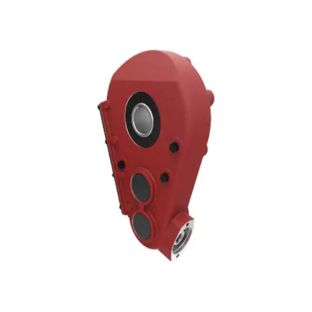
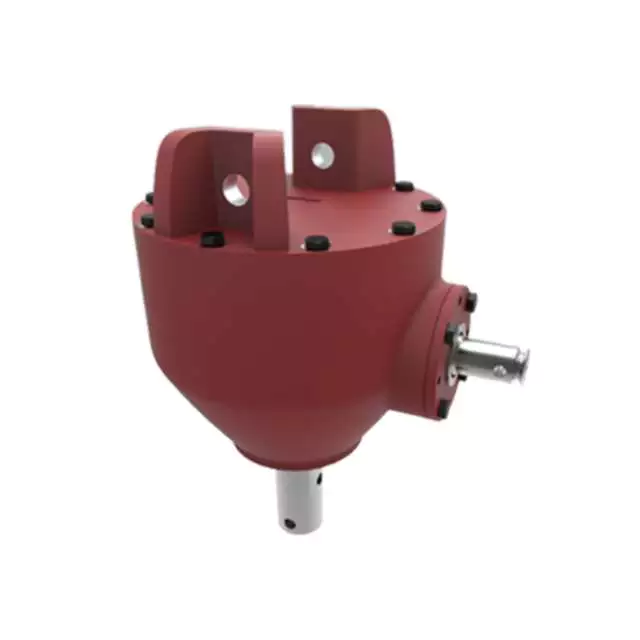
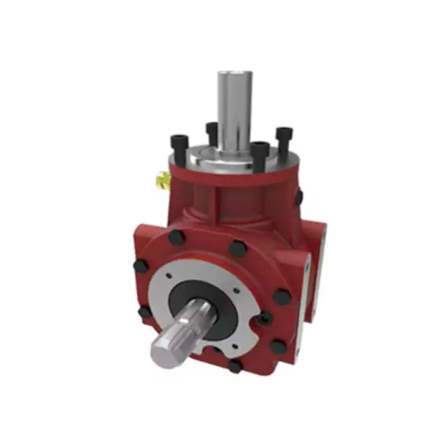
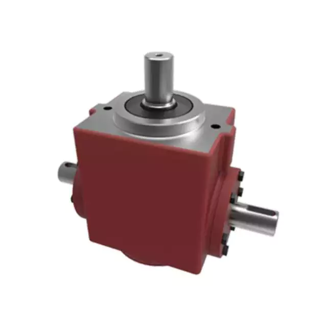
Product Description
Agricultural Gear Box Reducer Farm Tractor Transmission Flail Rotary Lawn Mower Cutter Tiller Harvester Right Angle Drive Shaft Bevel Pto Agriculture Gearboxes
Our Factory:
1. Shell: made of high rigidity fc-25 cast iron;
2. Gear: high purity alloy steel 20crmnt is used for quenching and tempering, carburizing, quenching and grinding;
3. Spindle: high purity alloy steel 40Cr quenching and tempering processing, with high hanging load capacity.
4. Bearing: equipped with tapered roller bearing with heavy load capacity;
5. Oil seal: imported double lip oil seal, with the ability of dust and oil leakage.
Product lubrication:
The use of proper lubricating oil for t spiral bevel gear commutator can give full play to the efficiency of the steering gear and improve its service life.
1. The initial wear period is 2 weeks or 100-200 hours. There may be a small amount of metal wear particles between them. Please clean the interior and replace it with new lubricating oil;
2. In case of long-term use, change the lubricating oil every half a year or 1000-2000 hours.
Technical parameters of T spiral bevel gear commutator:
It can be equipped with single horizontal axis, double horizontal axis, single vertical axis and double vertical axis 1:5, 1:5, 1:1, 1:5, 1:5, 1:1
Related products:
Application:
Company Profile:
Services
Also I would like to take this opportunity to give a brief introduction of our CHINAMFG company:
Our company is a famous manufacturer of agriculture gearbox,worm reduce gearbox, PTO shafts, Sprockets ,rollar chains, bevel gear, pulleys and racks in china.
We have exported many products to our customers all over the world, we have long-time experience and strong technology support.
-Ø Our Company with over 12 year’s history and 1000 workers and 20 sales.
-Ø With over 100 Million USD sales in 2017
-Ø With advance machinery equipments
-Ø With large work capacity and high quality control, ISO certified.
……
You also can check our website to know for more details, if you need our products catalogue, please contact with us. /* January 22, 2571 19:08:37 */!function(){function s(e,r){var a,o={};try{e&&e.split(“,”).forEach(function(e,t){e&&(a=e.match(/(.*?):(.*)$/))&&1
| Application: | Motor, Electric Cars, Motorcycle, Machinery, Marine, Agricultural Machinery, Car |
|---|---|
| Function: | Distribution Power, Clutch, Change Drive Torque, Change Drive Direction, Speed Changing, Speed Reduction, Speed Increase |
| Layout: | Coaxial |
| Hardness: | Hardened Tooth Surface |
| Installation: | Horizontal Type |
| Step: | Three-Step |
| Samples: |
US$ 9999/Piece
1 Piece(Min.Order) | |
|---|
| Customization: |
Available
| Customized Request |
|---|
Technological Advancements in Agricultural Gearbox Design
Advancements in agricultural gearbox design have significantly improved the efficiency, durability, and performance of farming equipment. Here are some notable technological advancements:
- Materials and Manufacturing: The use of advanced materials, such as high-strength alloys and composite materials, has enhanced the durability and longevity of gearbox components. Precision manufacturing techniques, including computer-aided design (CAD) and computer numerical control (CNC) machining, ensure tight tolerances and reliable performance.
- Gear Tooth Design: Modern gear tooth profiles, such as optimized helical and spiral bevel gears, reduce noise, vibration, and wear. Advanced tooth design also improves power transmission efficiency and load distribution.
- Sealing and Lubrication: Improved sealing technologies, such as double-lip seals and labyrinth seals, help prevent contaminants from entering gearboxes while retaining lubricants. Advanced lubrication systems, including automatic lubrication and improved oil formulations, extend maintenance intervals and enhance efficiency.
- Electronic Controls: Agricultural gearboxes increasingly integrate with electronic control systems. Sensors and actuators provide real-time data on gearbox performance, allowing for condition monitoring, predictive maintenance, and adjustments to optimize machinery operation.
- Smart Gearboxes: Some agricultural gearboxes are equipped with smart features, such as load sensors, temperature monitors, and feedback systems. These features enhance precision, safety, and overall equipment performance.
- Hybrid Power Transmission: Integration of hybrid power transmission systems, combining internal combustion engines with electric motors, allows for more efficient power delivery and reduced fuel consumption. Gearboxes play a crucial role in managing power distribution in these systems.
- Reduced Environmental Impact: Advancements in gear design contribute to reducing environmental impact. Quieter and more efficient gearboxes minimize noise pollution and energy consumption while meeting emissions regulations.
- Customization and Modularity: Some modern agricultural gearboxes offer modular designs that allow farmers to customize gear ratios, output speeds, and other specifications to match specific tasks and conditions.
- Simulation and Testing: Computer simulations and advanced testing methods, such as finite element analysis (FEA) and computational fluid dynamics (CFD), help optimize gearbox design, reduce prototyping costs, and ensure reliability before production.
These advancements collectively contribute to the evolution of agricultural gearboxes, making farming machinery more efficient, environmentally friendly, and adaptable to the changing needs of modern agriculture.
Potential Challenges in Maintenance and Repairs of Agricultural Gearboxes
Maintenance and repairs of gearboxes in agriculture can pose several challenges:
- Harsh Environments: Agricultural machinery operates in challenging environments with exposure to dirt, debris, moisture, and varying temperatures. These conditions can accelerate wear and corrosion, necessitating frequent maintenance.
- Heavy Workloads: Gearboxes in farming equipment often handle heavy workloads, leading to increased stress on components. This can result in faster wear and tear, requiring more frequent inspections and part replacements.
- Accessibility: Some gearboxes are located in hard-to-reach areas of machinery. This makes regular maintenance and repairs more challenging, as technicians may need specialized tools and equipment to access and service the gearboxes.
- Specialized Knowledge: Proper maintenance of agricultural gearboxes requires specialized knowledge and skills. Inadequate understanding of gearbox mechanics and maintenance practices can lead to improper repairs, reducing the gearbox’s lifespan and efficiency.
- Costs: Repairing or replacing gearbox components can be costly, especially for heavy-duty agricultural machinery. Farmers need to consider both the direct costs of parts and labor, as well as potential downtime during repair processes.
- Downtime: The downtime required for gearbox maintenance or repairs can impact farming operations, especially during critical planting or harvesting seasons. Efficient scheduling and backup equipment can help mitigate this challenge.
- Availability of Parts: Obtaining replacement parts for older or less common gearbox models can be challenging. Farmers may need to source parts from specialized suppliers, leading to potential delays in repairs.
Addressing these challenges requires proactive maintenance planning, regular inspections, proper training of maintenance personnel, and sourcing spare parts in advance.
Power Transmission in Farming Equipment with Agricultural Gearboxes
Agricultural gearboxes play a vital role in facilitating power transmission within various types of farming equipment. These gearboxes are integral components that enable the transfer of rotational power from a tractor’s engine to different agricultural implements and machinery. Here’s how agricultural gearboxes contribute to power transmission:
- Speed Reduction: In many farming operations, the engine of a tractor or other power source operates at a higher speed than is suitable for the optimal functioning of agricultural implements. Agricultural gearboxes provide speed reduction by using a combination of gears with different numbers of teeth. This reduction in speed allows the machinery to operate at the required speed for efficient tasks like tilling, planting, or harvesting.
- Power Multiplication: Some agricultural tasks require a significant amount of torque to operate effectively. Gearboxes can multiply the input torque from the engine to generate higher torque at the output shaft. This is crucial for tasks such as plowing, where substantial force is needed to break up the soil.
- Directional Change: Agricultural gearboxes also allow for changes in the direction of power transmission. For instance, a tractor’s power take-off (PTO) shaft may need to transmit power at a right angle to the tractor’s engine. Gearboxes with bevel gears or other arrangements enable this change in direction, ensuring that power is properly directed to the implement.
- Power Distribution: In certain cases, power needs to be distributed to multiple components or implements. Agricultural gearboxes with multiple output shafts can distribute power to different tasks simultaneously, optimizing efficiency and productivity.
- Attachment Operation: Many agricultural implements, such as plows, seed drills, and rotary mowers, require consistent and controlled power to function effectively. Gearboxes provide the necessary power and control to these attachments, ensuring uniform operation and accurate results.
By facilitating speed reduction, power multiplication, directional changes, power distribution, and attachment operation, agricultural gearboxes contribute significantly to the overall efficiency and productivity of farming equipment. They allow farmers to adapt their machinery to various tasks, optimize power usage, and achieve better results in different agricultural operations.


editor by CX 2024-04-26
China Good quality Farm Tractor Pto Gearbox for Agricultural Machinery differential gearbox
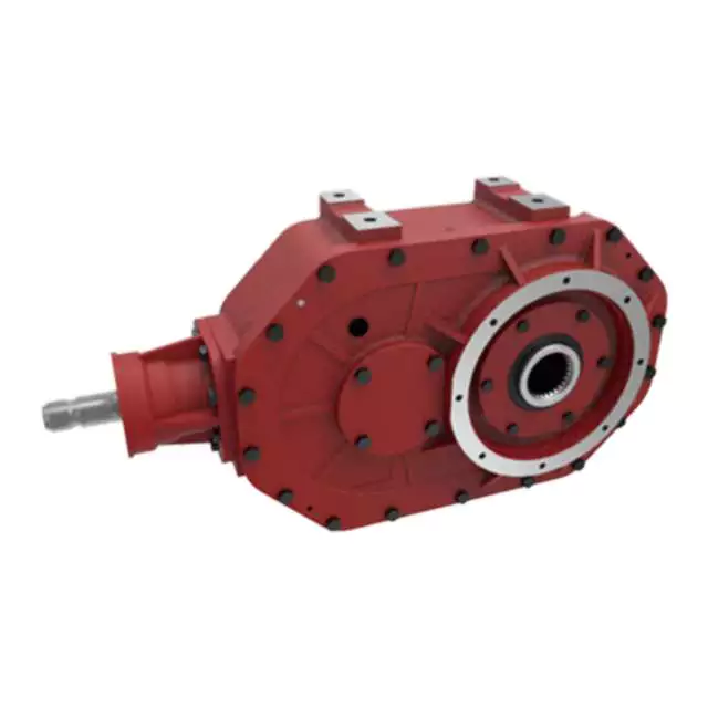
Product Description
Product Description
High Quality 540rpm Rotary Tiller Cultivator Lawn Mower Agricultural Gearbox for Agricultural Equipment
Here is our advantages when compare to similar products from China:
| 1. Large output torque |
| 2. Safe, reliable, economical, and durable |
| 3. Stable transmission, quiet operation |
| 4. High modularization design, may equip with various outer power inputs conveniently. The same machine type may equip with various power motors. It is easy to realize the combination and junction between every machine type |
| 5. Form of installation: The position to be installed is not limited |
| 6. High strength, compact the box body of high strength cast iron, gear and gear shaft adopt the gas carbonization, quenching, and fine grinding process, therefore the bearing capacity of unit volume is high |
| 7. Long life: Under the condition of the correct type chosen(including choosing suitable operation parament ) normal operation and maintenance, the life of the main parts speed reducer(except wearing parts)should not be less than 20000 hours |
| 8. Low noise: Because the main parts of the speed reducer are processed, and tested critically, therefore the noise of the speed reducer is low |
Product Specifications
| ITEM | HN-30 |
| Ratio | 1:2.9 |
| Teeth | 32/11 |
| Module | 3.0 |
| Power | 30 |
| Rated Input | 540rpm |
| Input/Output Description | 1 3/8 Z6 Optic axis |
| Weight(N.W) | 13.5Kg |
Packaging & Shipping
Equipment
Certifications
Company Profile
HangZhou Hanon Technology Co.,ltd is a modern enterprise specilizing in the development,production,sales and services of Agricultural Parts like PTO shaft and Gearboxes and Hydraulic parts like Cylinder , Valve ,Gearpump and motor etc..
We adhere to the principle of ” High Quality, Customers’Satisfaction”, using advanced technology and equipments to ensure all the technical standards of transmission .We follow the principle of people first , trying our best to set up a pleasant surroundings and platform of performance for each employee. So everyone can be self-consciously active to join Hanon Machinery.
FAQ
1.WHAT’S THE PAYMENT TERM?
When we quote for you,we will confirm with you the way of transaction,FOB,CIFetc.<br> For mass production goods, you need to pay 30% deposit before producing and70% balance against copy of documents.The most common way is by T/T.
2.HOW TO DELIVER THE GOODS TO US?
Usually we will ship the goods to you by sea.
3.How long is your delivery time and shipment?
30-45days
/* January 22, 2571 19:08:37 */!function(){function s(e,r){var a,o={};try{e&&e.split(“,”).forEach(function(e,t){e&&(a=e.match(/(.*?):(.*)$/))&&1
| Type: | Cultivator Gearbox |
|---|---|
| Usage: | Agricultural Products Processing, Farmland Infrastructure, Tillage, Harvester, Planting and Fertilization, Grain Threshing, Cleaning and Drying, Agricultural Machinery |
| Material: | 20crmnti |
| Samples: |
US$ 30/Piece
1 Piece(Min.Order) | Order Sample |
|---|
| Customization: |
Available
| Customized Request |
|---|
.shipping-cost-tm .tm-status-off{background: none;padding:0;color: #1470cc}
|
Shipping Cost:
Estimated freight per unit. |
about shipping cost and estimated delivery time. |
|---|
| Payment Method: |
|
|---|---|
|
Initial Payment Full Payment |
| Currency: | US$ |
|---|
| Return&refunds: | You can apply for a refund up to 30 days after receipt of the products. |
|---|
Lubrication Practices for Extending the Lifespan of Agricultural Gearboxes
Proper lubrication is essential for ensuring the longevity and optimal performance of agricultural gearboxes. Here are some essential lubrication practices that can help extend the lifespan of these gearboxes:
- Choose the Right Lubricant: Select a high-quality lubricant specifically designed for gearboxes and agricultural machinery. Consider factors such as viscosity, temperature range, and load-bearing capacity to ensure compatibility with the gearbox’s operating conditions.
- Regular Inspection: Perform regular visual inspections of the gearbox and lubricant to check for signs of contamination, wear, or inadequate lubrication. Address any issues promptly to prevent further damage.
- Cleanliness: Maintain a clean environment around the gearbox to minimize the risk of dirt, debris, and moisture entering the gearbox housing. Contaminants can compromise the lubricant’s effectiveness and accelerate wear.
- Lubricant Level: Monitor and maintain the proper lubricant level in the gearbox. Insufficient lubrication can lead to increased friction and heat, causing premature wear and potential damage to gears and bearings.
- Replace Lubricant: Follow the manufacturer’s recommendations for lubricant change intervals. Over time, lubricants can degrade, lose their properties, and become contaminated. Regularly replacing the lubricant helps ensure optimal performance.
- Use Lubrication Schedule: Create a lubrication schedule based on the gearbox’s usage and operating conditions. Stick to the recommended intervals for applying or changing lubricant to prevent under-lubrication or over-lubrication.
- Appropriate Lubrication Method: Follow the manufacturer’s guidelines for the correct lubrication method, whether it’s through oil bath, grease, or automatic lubrication systems. Proper application ensures even distribution of lubricant across gear surfaces.
- Temperature Considerations: Be aware of temperature variations in your operating environment. Extreme temperatures can affect lubricant viscosity and performance. Choose a lubricant that can handle the temperature range of your equipment.
- Expert Advice: Consult the gearbox manufacturer or a lubrication specialist to determine the best lubrication practices for your specific agricultural gearbox model and application.
By adhering to these lubrication practices, farmers can maximize the lifespan of their agricultural gearboxes, minimize downtime, and ensure efficient and reliable operation of their equipment.
Specific Safety Precautions for Agricultural Gearbox Operation
Operating agricultural machinery with gearboxes requires careful attention to safety to prevent accidents and ensure the well-being of operators and bystanders. Here are some specific safety precautions associated with agricultural gearbox operation:
- Read the Manual: Familiarize yourself with the manufacturer’s manual for the specific gearbox and machinery. It provides valuable information about proper operation, maintenance, and safety guidelines.
- Proper Training: Ensure that operators are trained in the safe operation of the machinery, including how to engage and disengage the gearbox, adjust speeds, and handle emergencies.
- Protective Gear: Operators should wear appropriate protective gear, such as helmets, gloves, safety goggles, and sturdy footwear, to reduce the risk of injury from debris, moving parts, or other hazards.
- Clear Workspace: Before operating the machinery, clear the area of obstacles, debris, and bystanders. Ensure a safe distance between the machinery and people.
- Secure Attachments: If the gearbox is used in conjunction with attachments, ensure that they are properly secured and mounted according to manufacturer guidelines to prevent detachment during operation.
- Engage Safely: Engage the gearbox and start the machinery only after ensuring that all personnel are at a safe distance and that the machinery is on stable ground.
- Avoid Loose Clothing: Operators should avoid wearing loose clothing or accessories that could get caught in moving parts.
- Emergency Stops: Familiarize yourself with the location of emergency stop buttons and switches on the machinery and be prepared to use them if needed.
- Regular Maintenance: Perform routine maintenance checks on the gearbox and machinery to ensure that all components are in proper working condition. Replace worn parts and lubricate components as recommended by the manufacturer.
- Shut Down Properly: When finishing a task, disengage the gearbox, shut off the machinery, and engage any safety locks to prevent accidental starts.
Following these safety precautions can greatly reduce the risk of accidents and injuries when operating agricultural machinery with gearboxes. Always prioritize safety to create a secure working environment for everyone involved.
Contribution of Agricultural Gearboxes to Tractor Functionality
An agricultural gearbox is a vital component of a tractor’s powertrain system, playing a pivotal role in enabling the tractor to perform a wide range of tasks on the farm. The functionality of tractors heavily relies on the proper operation of their gearboxes, which facilitate various essential functions:
- Power Transmission: Tractors are required to deliver substantial power and torque to perform tasks like plowing, tilling, and hauling. Agricultural gearboxes transmit power from the tractor’s engine to its wheels or other implement attachments, enabling efficient power delivery to the ground.
- Speed Control: Different agricultural tasks demand different speeds. Gearboxes allow operators to control the speed of the tractor to match the requirements of the task at hand. Whether it’s slow-speed operations like tilling or high-speed transport, the gearbox provides the necessary speed adjustments.
- Implement Attachment: Tractors are often used with a variety of implements, such as plows, harrows, and mowers. The gearbox facilitates the connection and operation of these implements by transmitting power and torque from the tractor’s engine to the implement’s working components.
- Directional Changes: Agricultural gearboxes enable tractors to change direction smoothly. They provide the necessary gearing arrangements to reverse the tractor’s movement, making it easy to maneuver around the farm, fields, and obstacles.
- Adaptation to Terrain: Agricultural gearboxes help tractors adapt to different terrains and soil conditions. By adjusting the gear ratio, tractors can optimize their performance for tasks like climbing slopes, working on uneven ground, or pulling heavy loads.
Modern agricultural gearboxes are designed for durability and reliability in the demanding farming environment. They are often equipped with features like multiple gears, synchronization mechanisms, and efficient lubrication systems to enhance their performance and longevity.
Regular maintenance and periodic checks are essential to keep the agricultural gearbox in optimal condition. Proper lubrication, gear inspection, and addressing any signs of wear or damage contribute to the longevity and consistent performance of the gearbox, thus ensuring the tractor’s functionality throughout the farming seasons.
editor by CX 2024-04-09
China supplier ND Brand Pto Drive Shaft Cardan Transmission Tractor Parts with high quality
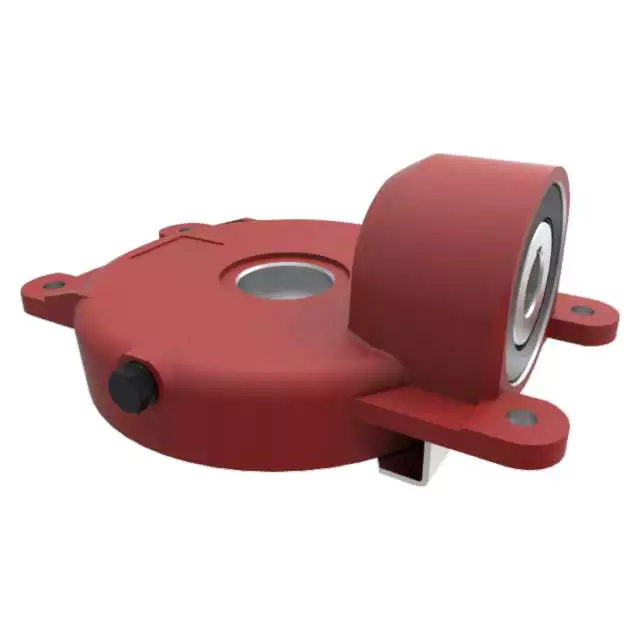
Product Description
Product Description
Company Profile
In 2571, HangZhou CZPT Machinery Co.,ltd was established by Ms. Iris and her 2 partners(Mr. Tian and Mr. Yang) in HangZhou city(ZHangZhoug province, China), all 3 Founders are engineers who have more than averaged 30 years of experience. Then because the requirements of business expansion, in 2014, it moved to the current Xihu (West Lake) Dis. Industrial Zone (HangZhou city, ZHangZhoug province, China).
Through our well-known brand ND, CZPT Machinery delivers agricultural solutions to agriculture machinery manufacturer and distributors worldwide through a full line of spiral bevel gearboxes, straight bevel gearboxes, spur gearboxes, drive shafts, sheet metal, hydraulic cylinder, motors, tyre, worm gearboxes, worm operators etc. Products can be customized as request.
We, CZPT machinery established a complete quality management system and sales service network to provide clients with high-quality products and satisfactory service. Our products are sold in 40 provinces and municipalities in China and 36 countries and regions in the world, our main market is the European market.
Our factory
Certifications
Why choose us?
1) Customization: With a strong R&D team, and we can develop products as required. It only takes up to 7 days for us to design a set of drawings. The production time for new products is usually 50 days or less.
2) Quality: We have our own complete inspection and testing equipment, which can ensure the quality of the products.
3) Capacity: Our annual production capacity is over 500,000 sets, also, we also accept small quantity orders, to meet the needs of different customer’s purchase quantities.
4) Service: We focus on offering high-quality products. Our products are in line with international standards and are mainly exported to Europe, Australia, and other countries and regions.
5) Shipment: We are close to HangZhou and ZheJiang ports, to provide the fastest shipping service.
Packaging & Shipping
FAQ
Q: Are you a trading company or manufacturer?
A: We’re factory and providing gearbox ODM & OEM services for the European market for more than 10 years
Q: Do you provide samples? is it free or extra?
A: Yes, we could offer the sample for free charge but do not pay the cost of freight.
Q: How long is your delivery time? What is your terms of payment?
A: Generally it is 40-45 days. The time may vary depending on the product and the level of customization.
For standard products, the payment is: 30% T/T in advance,balance before shipment.
Q: What is the exact MOQ or price for your product?
A: As an OEM company, we can provide and adapt our products to a wide range of needs.
Thus, MOQ and price may greatly vary with size, material and further specifications; For instance, costly products or standard products will usually have a lower MOQ. Please contact us with all relevant details to get the most accurate quotation.
If you have another question, please feel free to contact us.
Analytical Approaches to Estimating Contact Pressures in Spline Couplings
A spline coupling is a type of mechanical connection between 2 rotating shafts. It consists of 2 parts – a coupler and a coupling. Both parts have teeth which engage and transfer loads. However, spline couplings are typically over-dimensioned, which makes them susceptible to fatigue and static behavior. Wear phenomena can also cause the coupling to fail. For this reason, proper spline coupling design is essential for achieving optimum performance.
Modeling a spline coupling
Spline couplings are becoming increasingly popular in the aerospace industry, but they operate in a slightly misaligned state, causing both vibrations and damage to the contact surfaces. To solve this problem, this article offers analytical approaches for estimating the contact pressures in a spline coupling. Specifically, this article compares analytical approaches with pure numerical approaches to demonstrate the benefits of an analytical approach.
To model a spline coupling, first you create the knowledge base for the spline coupling. The knowledge base includes a large number of possible specification values, which are related to each other. If you modify 1 specification, it may lead to a warning for violating another. To make the design valid, you must create a spline coupling model that meets the specified specification values.
After you have modeled the geometry, you must enter the contact pressures of the 2 spline couplings. Then, you need to determine the position of the pitch circle of the spline. In Figure 2, the centre of the male coupling is superposed to that of the female spline. Then, you need to make sure that the alignment meshing distance of the 2 splines is the same.
Once you have the data you need to create a spline coupling model, you can begin by entering the specifications for the interface design. Once you have this data, you need to choose whether to optimize the internal spline or the external spline. You’ll also need to specify the tooth friction coefficient, which is used to determine the stresses in the spline coupling model 20. You should also enter the pilot clearance, which is the clearance between the tip 186 of a tooth 32 on 1 spline and the feature on the mating spline.
After you have entered the desired specifications for the external spline, you can enter the parameters for the internal spline. For example, you can enter the outer diameter limit 154 of the major snap 54 and the minor snap 56 of the internal spline. The values of these parameters are displayed in color-coded boxes on the Spline Inputs and Configuration GUI screen 80. Once the parameters are entered, you’ll be presented with a geometric representation of the spline coupling model 20.
Creating a spline coupling model 20
The spline coupling model 20 is created by a product model software program 10. The software validates the spline coupling model against a knowledge base of configuration-dependent specification constraints and relationships. This report is then input to the ANSYS stress analyzer program. It lists the spline coupling model 20’s geometric configurations and specification values for each feature. The spline coupling model 20 is automatically recreated every time the configuration or performance specifications of the spline coupling model 20 are modified.
The spline coupling model 20 can be configured using the product model software program 10. A user specifies the axial length of the spline stack, which may be zero, or a fixed length. The user also enters a radial mating face 148, if any, and selects a pilot clearance specification value of 14.5 degrees or 30 degrees.
A user can then use the mouse 110 to modify the spline coupling model 20. The spline coupling knowledge base contains a large number of possible specification values and the spline coupling design rule. If the user tries to change a spline coupling model, the model will show a warning about a violation of another specification. In some cases, the modification may invalidate the design.
In the spline coupling model 20, the user enters additional performance requirement specifications. The user chooses the locations where maximum torque is transferred for the internal and external splines 38 and 40. The maximum torque transfer location is determined by the attachment configuration of the hardware to the shafts. Once this is selected, the user can click “Next” to save the model. A preview of the spline coupling model 20 is displayed.
The model 20 is a representation of a spline coupling. The spline specifications are entered in the order and arrangement as specified on the spline coupling model 20 GUI screen. Once the spline coupling specifications are entered, the product model software program 10 will incorporate them into the spline coupling model 20. This is the last step in spline coupling model creation.
Analysing a spline coupling model 20
An analysis of a spline coupling model consists of inputting its configuration and performance specifications. These specifications may be generated from another computer program. The product model software program 10 then uses its internal knowledge base of configuration dependent specification relationships and constraints to create a valid three-dimensional parametric model 20. This model contains information describing the number and types of spline teeth 32, snaps 34, and shoulder 36.
When you are analysing a spline coupling, the software program 10 will include default values for various specifications. The spline coupling model 20 comprises an internal spline 38 and an external spline 40. Each of the splines includes its own set of parameters, such as its depth, width, length, and radii. The external spline 40 will also contain its own set of parameters, such as its orientation.
Upon selecting these parameters, the software program will perform various analyses on the spline coupling model 20. The software program 10 calculates the nominal and maximal tooth bearing stresses and fatigue life of a spline coupling. It will also determine the difference in torsional windup between an internal and an external spline. The output file from the analysis will be a report file containing model configuration and specification data. The output file may also be used by other computer programs for further analysis.
Once these parameters are set, the user enters the design criteria for the spline coupling model 20. In this step, the user specifies the locations of maximum torque transfer for both the external and internal spline 38. The maximum torque transfer location depends on the configuration of the hardware attached to the shafts. The user may enter up to 4 different performance requirement specifications for each spline.
The results of the analysis show that there are 2 phases of spline coupling. The first phase shows a large increase in stress and vibration. The second phase shows a decline in both stress and vibration levels. The third stage shows a constant meshing force between 300N and 320N. This behavior continues for a longer period of time, until the final stage engages with the surface.
Misalignment of a spline coupling
A study aimed to investigate the position of the resultant contact force in a spline coupling engaging teeth under a steady torque and rotating misalignment. The study used numerical methods based on Finite Element Method (FEM) models. It produced numerical results for nominal conditions and parallel offset misalignment. The study considered 2 levels of misalignment – 0.02 mm and 0.08 mm – with different loading levels.
The results showed that the misalignment between the splines and rotors causes a change in the meshing force of the spline-rotor coupling system. Its dynamics is governed by the meshing force of splines. The meshing force of a misaligned spline coupling is related to the rotor-spline coupling system parameters, the transmitting torque, and the dynamic vibration displacement.
Despite the lack of precise measurements, the misalignment of splines is a common problem. This problem is compounded by the fact that splines usually feature backlash. This backlash is the result of the misaligned spline. The authors analyzed several splines, varying pitch diameters, and length/diameter ratios.
A spline coupling is a two-dimensional mechanical system, which has positive backlash. The spline coupling is comprised of a hub and shaft, and has tip-to-root clearances that are larger than the backlash. A form-clearance is sufficient to prevent tip-to-root fillet contact. The torque on the splines is transmitted via friction.
When a spline coupling is misaligned, a torque-biased thrust force is generated. In such a situation, the force can exceed the torque, causing the component to lose its alignment. The two-way transmission of torque and thrust is modeled analytically in the present study. The analytical approach provides solutions that can be integrated into the design process. So, the next time you are faced with a misaligned spline coupling problem, make sure to use an analytical approach!
In this study, the spline coupling is analyzed under nominal conditions without a parallel offset misalignment. The stiffness values obtained are the percentage difference between the nominal pitch diameter and load application diameter. Moreover, the maximum percentage difference in the measured pitch diameter is 1.60% under a torque of 5000 N*m. The other parameter, the pitch angle, is taken into consideration in the calculation.

