Description
Flange Ground Helical Gear
DIN6 Grade 5 precision | 20CrMnTi alloy | HRC 55–60 surface hardness — engineered for demanding automation and linear motion systems across the UK industrial sector.
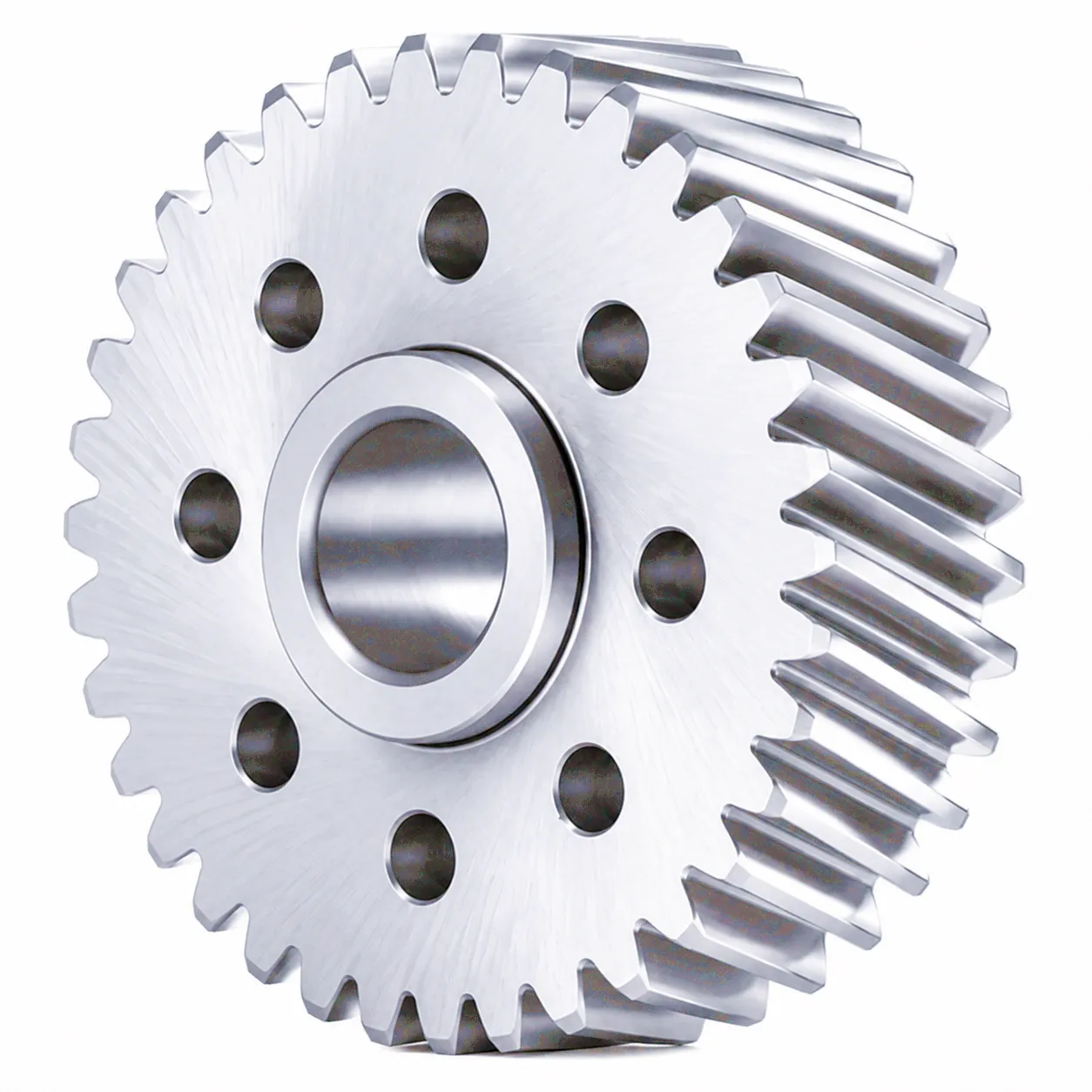 What Makes This Gear Different?
The flange ground helical gear is a highly engineered component used wherever smooth power transmission and positional accuracy matter. Ground tooth flanks give it an edge over standard cut gears — reduced noise, tighter tolerances, and a substantially longer service life in repetitive-cycle environments. Whether you are running a CNC machining centre in Birmingham, a packaging line in Manchester, or a robotics cell in the East Midlands, this gear delivers the repeatability your process demands. Its flange-mount design simplifies integration into rack-and-pinion drives without additional adapters, saving both engineering time and assembly cost.
DIN6 Grade 5
HRC 55–60
Ready to source flange ground helical gears for your UK project?
Custom modules, bore sizes, and coatings available on request.
Technical Specifications
All data verified against factory drawings. Dimensions in millimetres unless otherwise stated.
Technical Requirements
| Precision Grade | DIN6 International Grade 5 |
| Material | 20CrMnTi alloy steel |
| Tooth Type | Helical tooth |
| Helix Angle | 19 deg 31′ 42″ |
| Surface Hardness | Carburized HRC 55–60 |
| Manufacturing | Tooth surface grinding |
YMCLK Series — Flange Ground Helical Gear (Unit: mm)
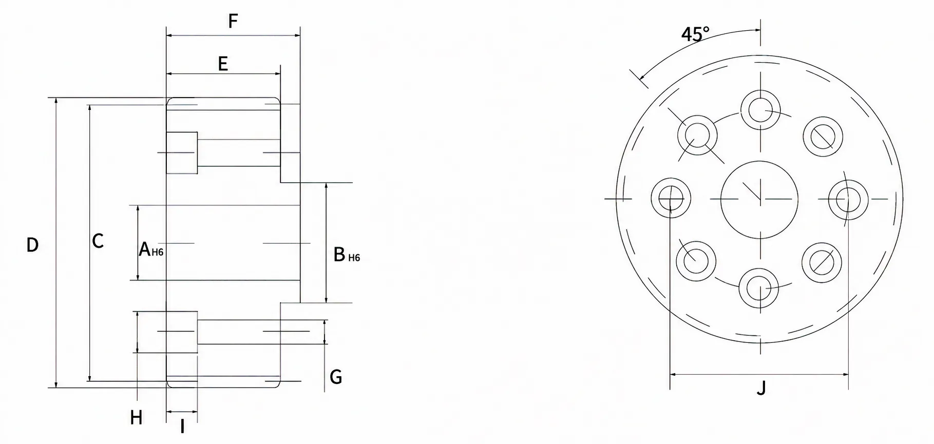
| Code | Module | Tooth No. | AH6 | BH6 | C | D | E | F | G | H | I | J |
|---|---|---|---|---|---|---|---|---|---|---|---|---|
| YMCLK26 | 2 | 26 | 15 | 20 | 55.174 | 60.800 | 26 | 29.0 | 5.5 | 10 | 12 | 31.5 |
| YMCLK27 | 2 | 27 | 15 | 20 | 57.296 | 61.296 | 30 | 33.5 | 5.5 | 10 | 11 | 31.5 |
| YMCLK29 | 2 | 29 | 15 | 20 | 61.540 | 67.200 | 26 | 29.0 | 5.5 | 10 | 12 | 31.5 |
| YMCLK35 | 2 | 35 | 15 | 20 | 74.272 | 79.800 | 26 | 29.0 | 5.5 | 10 | 12 | 31.5 |
| YMCLK29-20 | 2 | 29 | 20 | 25 | 61.540 | 67.200 | 26 | 30.0 | 6.6 | 11 | 14 | 40 |
| YMCLK33 | 2 | 33 | 20 | 31.5 | 70.028 | 75.599 | 26 | 30.0 | 6.6 | 11 | 14 | 50 |
| YMCLK35 | 2 | 35 | 20 | 31.5 | 74.300 | 79.500 | 26 | 30 | 6.6 | 11 | 14 | 50 |
| YMCLK36 | 2 | 36 | 20 | 31.5 | 76.394 | 80.394 | 30 | 34.0 | 6.6 | 11 | 8 | 50 |
| YMCLK37 | 2 | 37 | 20 | 31.5 | 78.517 | 84.200 | 26 | 30.0 | 6.6 | 11 | 14 | 50 |
YMCL Series — Flange Ground Helical Gear (Unit: mm)
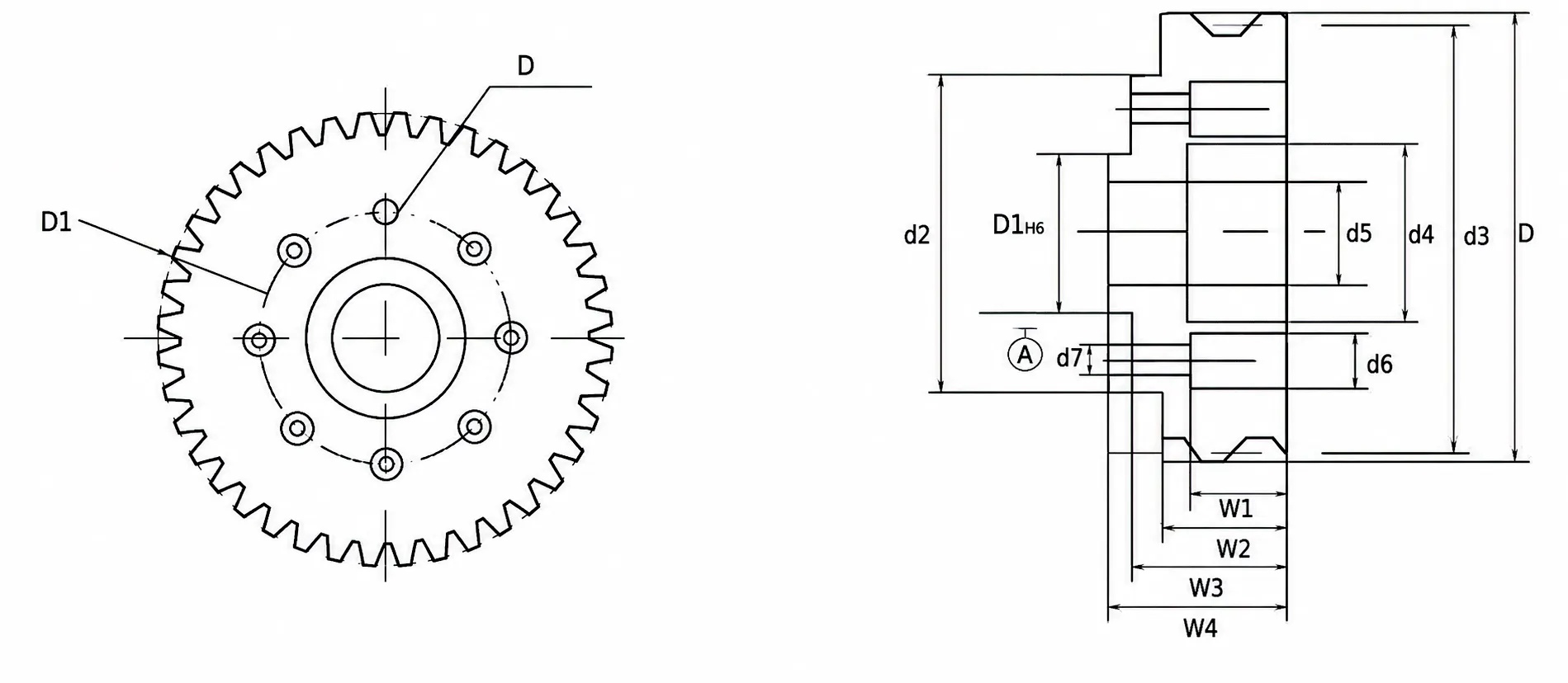
| Code | Module | Tooth No. | d1H6 | d2 | d3 | d4 | d5 | d6 | d7 | W1 | W2 | W3 | W4 | DH6 | D1 |
|---|---|---|---|---|---|---|---|---|---|---|---|---|---|---|---|
| YMCL37 | 2 | 37 | 31.500 | 63 | 78.52 | 35 | 20 | 1.1 | 6.6 | 14 | 24 | 34 | 40 | 6 | 50 |
| YMCL40 | 2 | 40 | 31.500 | 63 | 84.88 | 35 | 21 | 1.1 | 6.4 | 14 | 26 | 31 | 37 | 6 | 50 |
How the Flange Ground Helical Gear Works
Operating Principle
Helical gears transmit rotation between parallel shafts with tooth engagement that progresses gradually along the tooth face rather than all at once. This staggered contact distributes load over more tooth surface area at any given instant, translating directly to lower vibration, quieter running, and superior torque capacity compared to spur gears of equivalent size. The ground tooth surface on this flange variant refines that geometry to within DIN6 Grade 5 tolerances, meaning pitch error and tooth profile error are held to fractions of a micrometre — critical for servo-driven positioning systems where backlash directly impacts accuracy.
20CrMnTi Alloy Steel
The choice of 20CrMnTi is deliberate. This chromium-manganese-titanium alloy offers an excellent combination of core toughness and surface hardenability. After carburizing and quenching, the tooth flanks reach HRC 55–60 while the gear body retains meaningful impact resistance — preventing the brittle fracture that can occur in fully hardened components under shock loading. For UK manufacturing environments where production schedules cannot accommodate unplanned downtime, this material selection is a practical insurance policy as much as a performance specification.
Application Scenarios
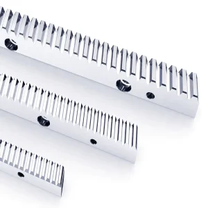
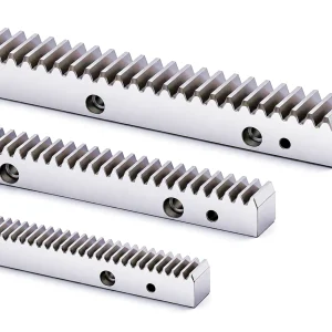
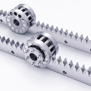
Flange ground helical gears are specified across a broad range of high-precision applications. In CNC machining centres and multi-axis gantries, they form the drive pinion in rack-and-pinion assemblies alongside a Rectangular Guide Rail or a V-Type Ground Helical Guide Rack. They also appear in robotic arm joints, precision laser cutting tables, automated warehouse retrieval systems, and high-cycle packaging equipment — any scenario where smooth, repeatable linear or rotary positioning is non-negotiable.
6 Engineering Advantages Worth Knowing
DIN5
Grade 5 precision — tighter than the industry standard for comparable ground gears
HRC60
Peak surface hardness after carburizing, extending tooth wear life significantly
Low dB
Helical tooth geometry reduces impulse noise vs. spur equivalents at the same pitch speed
Flange
Integrated flange mount cuts assembly time and eliminates the need for separate adapters
Custom
Non-standard bore, keyway, module, and coating options available from factory
Stock UK
Common YMCLK and YMCL series codes held for fast dispatch to mainland UK addresses
Products That Work Alongside This Gear
A flange ground helical gear rarely operates in isolation. Matching it with the correct guide rail or rack ensures the complete drive system meets the accuracy and load ratings your application demands. The two products below are designed to complement this gear directly and are stocked in the same facility, simplifying procurement and reducing lead times for UK buyers.
Rectangular Guide Rail
Provides the linear reference surface for rack-and-pinion drives. Designed for high load and rigidity, compatible with this gear’s flange-mount geometry.
V-Type Ground Helical Guide Rack
Ground helical rack that meshes directly with this gear series. V-type geometry aids self-alignment and reduces installation sensitivity for CNC gantries and automation slides.
How UK Manufacturers Are Using This Gear
The following case reflects a real supply project completed with a UK-based industrial customer. Details have been summarised for commercial confidentiality.
Midlands, UK · Automated Pallet Transfer System · 2024
Reducing Drive Noise on a High-Cycle Conveyor Line
A contract manufacturer producing automotive sub-assemblies in Coventry ran into persistent noise and premature wear on their pallet shuttle system after just eight months of operation. The original spur-cut pinions had been sourced locally on price alone. After switching to YMCLK35 flange ground helical gears paired with a V-Type Ground Helical Guide Rack, noise levels dropped measurably and the first inspection at 12 months showed tooth surfaces within original tolerance. The customer now sources YMCLK33 and YMCLK35 codes on a quarterly call-off contract, having standardised on this gear series across three production cells.
“We specified YMCLK36 for a new laser gantry build and the dimensional accuracy was exactly as stated. The flange fit straight to our servo output without any rework — that saved us a full day of machining. Will be using these on the next three machines.”
— Design Engineer, Yorkshire CNC Integrator
“Price per unit was competitive compared to European alternatives, and lead time from order to delivery at our Gloucester facility was under three weeks. The surface finish on the tooth flanks is notably better than what we had been buying. Backlash is within spec with no adjustment needed.”
— Procurement Manager, South West Automation Company
“We needed a non-standard bore on YMCL40 and the team at Ever-Power accommodated the modification without a significant price uplift or extended lead time. Technical drawings were provided promptly. Good communication throughout — would not hesitate to request custom specs again.”
— R&D Lead, Scottish Robotics OEM
Factory-Direct with Full Customisation Service
Every flange ground helical gear leaves our production facility already inspected against DIN6 Grade 5 using CMM verification and surface roughness testing. The factory operates dedicated gear grinding lines configured for helical tooth forms, which means profile and lead tolerances are held consistently across production batches — not just on sample pieces. Beyond standard catalogue codes, the engineering team handles a substantial volume of custom orders each month. Common modifications requested by UK customers include alternative bore diameters and keyway configurations, module changes (typically M1.5 to M4), bespoke hub lengths for specific servo motor interfaces, and black oxide or phosphate coatings for improved corrosion resistance in humid workshop environments. Quantities from single prototypes through to production runs of several hundred pieces are all within normal scope. If your drawing calls for something outside the standard range, send your specification to our team and a technical response is provided within one working day.
Common Questions from UK Buyers
Ready to Place Your Order or Request a Sample?
Our technical team is ready to support UK engineering and procurement teams with specifications, custom drawings, and competitive pricing.
edit by gzl